Table of Contents
Advertisement
Quick Links
RH4Z2501-KIT
Evaluation Board Quick Start Guide
This document provides a step by step guide to use the RH4Z2501-KIT, its main features, and the necessary
hardware setup to implement an IO-link network using different approaches.
Target Device: RH4Z2501: IO-Link transceiver with integrated protection.
Contents
1.
Requirements ................................................................................................................................................. 2
1.1
Hardware Requirements ........................................................................................................................ 2
1.2
Software Requirements ......................................................................................................................... 2
2.
Setup and Configuration of ZSSC328x ........................................................................................................ 2
2.1
Hardware Setup ..................................................................................................................................... 2
2.2
Firmware ................................................................................................................................................ 3
2.3
Data Visualization .................................................................................................................................. 4
3.
Glossary ........................................................................................................................................................ 10
4.
Revision History .......................................................................................................................................... 10
Figures
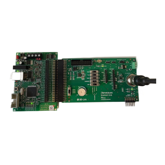
Figure 1. Hardware Setup ......................................................................................................................................... 3
Figure 2. Importing IODD Files into TMG IO-Link device tool .................................................................................. 4
Figure 3. Search Master ........................................................................................................................................... 4
Figure 4. Master Discovery Window ......................................................................................................................... 5
Figure 5. Device detection ........................................................................................................................................ 5
Figure 6. Takeover Devices ...................................................................................................................................... 5
Figure 7. Opening Process Data Tab ....................................................................................................................... 6
Figure 8. Reading Data Values................................................................................................................................. 6
Figure 9. Selecting COM Mode by SW7 ................................................................................................................... 7
Figure 10. Reset by SW6 .......................................................................................................................................... 7
Figure 11. Deleting IODD Files ................................................................................................................................. 7
Figure 12. New Device Takeover ............................................................................................................................. 8
Figure 13. Changed COM Mode............................................................................................................................... 8
Figure 14. Changing Parameter Values ................................................................................................................... 9
Figure 15. Parameter Transfer Status Verification ................................................................................................... 9
Figure 16. Read Values ............................................................................................................................................ 9
R36UZ0024ED0100 Rev.1.00
Jun 23, 2023
Quick Start Guide
Page 1
© 2023 Renesas Electronics
Advertisement
Table of Contents

Related Manuals for Renesas RH4Z2501-KIT


Summary of Contents for Renesas RH4Z2501-KIT
-
Page 1: Table Of Contents
RH4Z2501-KIT Evaluation Board Quick Start Guide This document provides a step by step guide to use the RH4Z2501-KIT, its main features, and the necessary hardware setup to implement an IO-link network using different approaches. Target Device: RH4Z2501: IO-Link transceiver with integrated protection. -
Page 2: Requirements
1. Requirements The hardware and software ecosystem have been developed to provide you a quick start and an easy understanding of the IO-Link fieldbus functionalities and specificities. Contact the local Renesas representatives to obtain the described devices and development boards. -
Page 3: Firmware
R9 and it also configures the RH4Z2501 via OWI. After the initial setup, write/read the processed data via the IO-link device stack provided by TMG. Note: Renesas do not provide the binary file to be flashed to the target for confidentiality reasons. Therefore, no Firmware updates needs to be performed to the target. -
Page 4: Data Visualization
RH4Z2501-KIT Quick Start Guide Data Visualization Follow these steps to have the read data initially available: 1. Run “IO-Link Device Tool V5.1.exe”. 2. Import the IODD file inside the tool by the following steps: a. Open the ‘Import IODD’ window by clicking on Option/Import IODD menu. -
Page 5: Figure 4. Master Discovery Window
RH4Z2501-KIT Quick Start Guide b. Select the correct IO-Link Master in the ‘Master Discovery’ window, with a double click, see Figure 4. Figure 4. Master Discovery Window c. Click on the green lecture button and on the loop to run a device detection, see Figure 5. -
Page 6: Figure 7. Opening Process Data Tab
RH4Z2501-KIT Quick Start Guide 4. Process data readings by following these steps: a. Open the ‘Process Data’ tab in the ‘RH4Z2501_KIT’ window, see Figure 7. Figure 7. Opening Process Data Tab b. Select the necessary values, see Figure 8. Figure 8. Reading Data Values R36UZ0024ED0100 Rev.1.00... -
Page 7: Figure 9. Selecting Com Mode By Sw7
RH4Z2501-KIT Quick Start Guide 5. Select the COM mode by following these steps: a. Set the Switch 7 to the selected COM mode, see Figure 9. Figure 9. Selecting COM Mode by SW7 b. Press Switch 6 to reset the ZSSC328x firmware, see Figure 10. -
Page 8: Figure 12. New Device Takeover
RH4Z2501-KIT Quick Start Guide d. Re-run a device detection by clinking on the loop and then on ‘Takeover devices into engineering’, see Figure 12. Figure 12. New Device Takeover The changed COM mode is visible in the ‘Bitrate’ field of the ‘RH4Z2501_KIT’ window, see Figure 13. -
Page 9: Figure 14. Changing Parameter Values
RH4Z2501-KIT Quick Start Guide 6. Activate output data threshold by following these steps: a. Open the ‘Parameter’ tab of the ‘RH4Z2501_KIT’ window. b. Set the thresholds in the tables by entering the values to the fields, see Figure 14 c. Write the NVRAM by clicking on the icon, see Figure 14. -
Page 10: Glossary
RH4Z2501-KIT Quick Start Guide 3. Glossary Term Description Analog Front End General User Interface IODD Input Output Device Description One Wire Interface 4. Revision History Revision Date Description Jun 23, 2023 Initial release. R36UZ0024ED0100 Rev.1.00 Page 10 Jun 23, 2023... - Page 11 Renesas' products are provided only subject to Renesas' Terms and Conditions of Sale or other applicable terms agreed to in writing. No use o any Renesas resources expands or otherwise alters any applicable warranties or warranty disclaimers for these products.
Need help?
Do you have a question about the RH4Z2501-KIT and is the answer not in the manual?
Questions and answers