
Related Manuals for GeoVision GV-PPTZ7300


Summary of Contents for GeoVision GV-PPTZ7300
- Page 1 GV-Panoramic PTZ Camera User's Manual Before attempting to connect or operate this product, PPTZV10-A-EN please read these instructions carefully and save this manual for future use.
- Page 2 GeoVision. Every effort has been made to ensure that the information in this manual is accurate. GeoVision, Inc. makes no expressed or implied warranty of any kind and assumes no responsibility for errors or omissions. No liability is assumed for incidental or consequential damages arising from the use of the information or products contained herein.
- Page 3 Preface Welcome to the GV-Panoramic PTZ IP Camera User’s Manual. This Manual is designed for the following model and firmware version: Model Model Number Firmware Version Panoramic PTZ Camera GV-PPTZ7300 V1.0...
-
Page 4: Table Of Contents
Contents Naming and Definition ............vii Note for Connecting to GV-VMS ..........viii Note for Recording ..............ix Note for Installing Camera............x Chapter 1 Introduction ............1 1.1 Key Features ......................5 1.2 Packing List ......................7 1.3 System Requirement ..................... 8 1.4 Optional Accessories ..................... 9 1.5 Physical Description....................10 1.6 Installation ......................11 1.7 Connecting the Camera ..................17... - Page 5 3.2.3 Snapshot of a Live Video ................40 3.2.4 Video Recording ..................40 3.2.5 Wide Angle Lens Dewarping..............41 3.2.6 Picture-in-Picture and Picture-and-Picture View........42 3.2.7 Alarm Notification..................44 3.2.8 Video and Audio Configuration ..............46 3.2.9 Remote Configuration ................48 3.2.10 Camera Name Display................48 3.2.11 Image Enhancement................48 3.2.12 I/O Control ....................49 3.2.13 Visual Automation...................50 3.2.14 PTZ Control ....................51...
- Page 6 4.5.2 I/O Monitoring Settings ................91 4.6 Remote ViewLog ....................92 4.7 Network ........................93 4.7.1 LAN ......................93 4.7.2 Advanced TCP/IP ..................95 4.8 Management......................98 4.8.1 Date and Time Settings ................98 4.8.2 Storage Settings ..................100 4.8.3 User Account ..................105 4.8.4 Log Information..................106 4.8.6 Language....................109 Chapter 5 PTZ Control Panel ..........110 5.1 Preset Settings ....................113 5.2 Cruise Settings ....................114...
- Page 7 Chapter 7 Advanced Applications ........142 7.1 Upgrading System Firmware................142 7.1.1 Using the Web Interface .................143 7.1.2 Using the GV-IP Device Utility ..............144 7.2 Backing Up and Restoring Settings..............146 7.2.1 Backing Up the Settings................146 7.2.2 Restoring the Settings................147 7.3 Restoring to Factory Default Settings..............148 7.3.1 Using the Web Interface .................148 7.3.2 Directly on the Camera ................148 7.4 Changing Password....................149...
- Page 8 Appendix ................173 A. Settings for Internet Explore 8 or later..............173 B. RTSP Protocol Support...................174 C. The CGI Command....................175...
-
Page 9: Naming And Definition
Naming and Definition GV-VMS GeoVision Video Management System for IP cameras. GeoVision video streaming server designed for large-scale video GV-Recording surveillance deployments which can record up to 128 channels Server while transmitting up to 300 channels. -
Page 10: Note For Connecting To Gv-Vms
Note for Connecting to GV-VMS The GV-Panoramic PTZ IP Camera is designed to work with GV-VMS, a video management system. Note the following when the camera is connected to GV-VMS: 1. By default, the images are recorded to the memory card inserted in the GV- Panoramic PTZ IP Camera. -
Page 11: Note For Recording
Note for Recording 1. By default, the images are recorded to the memory cards inserted in the GV-PPTZ Camera. Make sure the Write recording data into local storage option (see 4.1.1 Video Settings) is enabled. If this option is disabled, the camera will stop recording to the memory card while the live view is accessed through Web browsers or other applications. -
Page 12: Note For Installing Camera
Note for Installing Camera When installing GV-Panoramic PTZ IP Camera, be sure that: 1. The camera is set up above the junction box to prevent water from entering the camera along the cables. 2. Any PoE, power, audio and I/O cables are waterproofed using waterproof silicon rubber or the like. -
Page 13: Chapter 1 Introduction
Introduction Chapter 1 Introduction The Panoramic PTZ IP Camera is a 2-in-1 hybrid camera that includes a 5 MP fisheye panoramic camera and a 2 MP IP Speed Dome. The fisheye camera allows you to monitor all angles of a location, while the speed dome can instantly point toward an area with just one click on the fisheye live view. - Page 14 The Integrated interface shows the live views of both the speed dome and the fisheye camera. Once the fisheye setting is enabled, you can click on the fisheye live view and the speed dome will point toward the selected location. Integrated Live View-Expansive Mode 2 MP Speed Dome 5 MP Fisheye Camera...
- Page 15 Introduction The fisheye interface allows you to see the fisheye live view and configure the settings that apply to the fisheye part, as well as general settings for the entire camera. Figure 1-2 The speed dome interface allows you to see the speed dome live view and configure the settings that apply to the speed dome part only.
- Page 16 Below is a table showing the settings available on the three Web interfaces. Web Interfaces Settings Fisheye: Speed Dome: Integrated Interface GV-PPTZ7300-FE GV-PPTZ7300-SD Video and Motion O Video Settings O Video Settings O Motion Detection O Motion Detection O Privacy Mask...
-
Page 17: Key Features
Introduction 1.1 Key Features • Panoramic fisheye camera (FE) integrated with a PTZ speed dome (SD) • Image sensor GV-Panoramic PTZ Camera Image Sensor Panoramic – FE 1/2.5’’ progressive scan CMOS PTZ - SD 1/2.86’’ progressive scan CMOS • Dual streams from H.264 or MJPEG •... - Page 18 • Defog • Tampering alarm • Privacy mask • Visual automation • Text overlay • 31 languages on Web interface • ONVIF (Profile S) conformant • Recording assigned by GV-Edge Recording Manager (Windows & Mac) • More storage option -...
-
Page 19: Packing List
Introduction 1.2 Packing List • • Panoramic PTZ IP Camera Data Cable • • Mounting Bracket Mounting Cap • • Tube 2 mm Hex Key • • 3 mm Hex Key 5 mm Hex Key • • Rubber ring RJ-45 Connector •... -
Page 20: System Requirement
1.3 System Requirement To operate the camera through a web browser, make sure your PC has good network connection, and meet the following system requirement: 64-bit Windows 7 / 8 / 8.1 / 10 / Server 2008 R2 / Server 2012 R2 GV-VMS V15.10.1.0 with patch files or later versions •... -
Page 21: Optional Accessories
GV-PA901 The GV-PA901 is a Power over Ethernet (PoE) adapter designed to provide power to the IP device through a single Power over Ethernet (PoE) Ethernet cable to GV-PPTZ7300. Adapter GV-Mount Accessories The GV-Mount Accessories provides a comprehensive lineup of accessories for installation on ceiling, wall and pole. -
Page 22: Physical Description
1.5 Physical Description Figure 1-4 Name Function Flashes when the camera is powering on and loading Status LED default settings. Resets all configurations to default factory settings. See Default Button 7.3 Restoring to Factory Default Settings. Speed Dome SD Card Inserts a micro SD card (SD/SDHC, version 2.0, Class 10) Slot to store recording data from the speed dome. -
Page 23: Installation
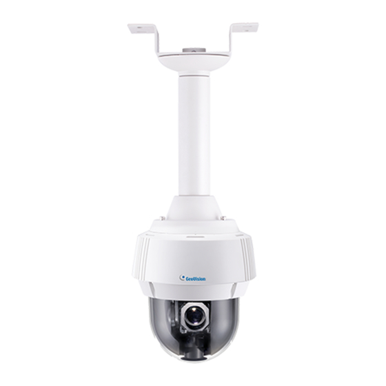
Introduction 1.6 Installation The Panoramic PTZ Camera can be mounted on the ceiling using the supplied Straight Tube Mount. Make sure the ceiling has enough strength to support the camera and the mount. Required items: • Screws for ceiling x 4 (Self-prepared) Optionally extend with: •... - Page 24 Insert the desiccants to the camera. A. Remove the camera cover using the 3 mm hex key. Figure 1-5 B. Insert your SD cards into the SD card slots for the fisheye camera and the speed dome. Figure 1-6 C. Insert one desiccant pack to the indicated place. Figure 1-7 IMPORTANT: Be sure the desiccant is concealed in the camera within 2 minutes of opening the desiccant pack.
- Page 25 Introduction D. Secure the camera cover with the 3 mm hex key. Make sure the first two screws to be tightened are diagonal to each other. Assemble the supplied mounting bracket, tube and mounting cap by rotating the parts together. Figure 1-8 Make sure the tubes are properly screwed.
- Page 26 B. Slide the cap and components through the Ethernet cable as shown below, and attach the supplied RJ-45 connector to the cable. Figure 1-11 C. Insert the Ethernet cable to the LAN port, move the cap and the components toward the LAN port, and secure the cap tightly.
- Page 27 Introduction E. Fasten the data cable with the mounting plate and the rubber ring. Figure 1-14 F. Insert the pin connectors of the data cable to the indicated area. Figure 1-15 G. Secure the mounting plate with the 3 mm hex key. Thread the cables through the tube.
- Page 28 B. Push the rivets into the holes on the mounting cap and rotate clockwise to lock the position. Figure 1-17 C. Rotate the camera onto the mounting cap and secure using the 5 mm hex key. Figure 1-18 Secure the assembled camera to the ceiling with 4 self-prepared screws.
-
Page 29: Connecting The Camera
Introduction 1.7 Connecting the Camera The GV-PPTZ7300 comes with a data cable that allows you to connect to the power adapter, microphone, speaker, and any I/O devices. Follow the steps below to connect the camera. Connect Power using one of the following methods: •... - Page 30 Hub / Router. Connect one end of an Ethernet cable to the PoE 10 / 100 port on the GV-PA901, and the other end to the GV-PPTZ7300. Connect the GV-PA901 Power Adapter to the power outlet.
-
Page 31: Chapter 2 Getting Started
Getting Started Chapter 2 Getting Started This section provides basic information to get the camera working on the network. 2.1 Installing on a Network These instructions describe the basic connections to install the camera on the network. Using a standard network cable, connect the camera to your network. Connect power using one of the methods. -
Page 32: Checking The Dynamic Ip Address
IP devices connected in the same LAN. Click the Name or Mac Address column to sort. You will see two devices listed: GV-PPTZ7300-FE and GV-PPTZ7300-SD. Figure 2-1 Click on the IP address of GV-PPTZ7300-FE and select Web Page. Figure 2-2... - Page 33 Getting Started The login page of the integrated interface appears. Type the default ID and password admin and click Apply. Figure 2-3...
-
Page 34: Assigning An Ip Address
2. In both Login and Password fields, type the default value admin. Click Apply. 3. In the left menu, select GV-PPTZ7300 – FE under Camera Setting. You will be directed to the Web interface of the fisheye camera. Figure 2-4... - Page 35 Getting Started 4. Type the default value admin again and click Apply Figure 2-5 5. Select Static IP address. Type IP Address, Subnet Mask, Router/Gateway, Primary DNS and Secondary DNS in the Configure connection parameters section. 6. Click Apply. The integrated interface and fisheye interface are now accessible by entering the assigned IP address on the Web browser.
-
Page 36: Configuring The Basics
2.2 Configuring the Basics Once the camera is properly installed, the following important features can be configured using the browser-based configuration page and are discussed in the following sections in this manual: • Date and time adjustment: see 4.8.1 Date and Time Settings. •... -
Page 37: Chapter 3 Accessing The Camera
4. A video image, similar to the example in Figure 3-2, is now displayed in your browser. Note: To enable the updating of images in Microsoft Internet Explorer, you must set your browser to allow ActiveX Controls and perform a one-time installation of GeoVision’s ActiveX component onto your computer. -
Page 38: The Integrated Web Interface
Expansive Mode ► PIP Mode (Left / Right) ▼ Camera Setting ► GV-PPTZ7300 – FE ► GV-PPTZ7300 - SD Figure 3-2 Expansive Mode Under the Expansive Mode, the speed dome live view is placed on the right and the fisheye live view is placed on the left. - Page 39 You can link to the individual Web interface of the fisheye camera and the speed dome. GV-PPTZ7300-FE: Refer to Chapters 3 (3.2 The Individual Fisheye and Speed Dome Interface) and 4 of this manual to see instructions on the fisheye Web interface.
-
Page 40: The Live View Window
3.1.2 The Live View Window Live View Buttons In the integrated interface, the following buttons are available under the speed dome live view. Figure 3-5 No. Name Function 1 Play Plays the live video of the fisheye camera and the speed dome. 2 Stop Stops playing video from the fisheye camera and the speed dome. - Page 41 Accessing the Camera Right-Clicking the Live View Window Right-click the fisheye live view to access the fisheye functions below: Figure 3-6 Snapshot: Takes a snapshot of the fisheye live view Full Screen: Switches the fisheye view to full screen. Resolution: Displays the resolution of the fisheye camera on live view. Visual Automation: The Visual Automation allows you to change the current state of the electronic device by simply clicking on its image, e.g.
- Page 42 Enabling Fisheye Functions To enable the fisheye options, right-click the Fisheye live view and select Geo Fisheye. Once enabled, you can click on the fisheye live view, and the camera will turn toward the selected location. Figure 3-7 Right-click the image again and select Fisheye Option to see the following options. Image Alignment: By default, the image should be properly aligned already.
- Page 43 Accessing the Camera Camera Position: This option is only available under 360 View. You can temporarily set the camera position to Ground instead of the default Ceiling if you want to test the camera view prior to installing the camera on the ceiling.
-
Page 44: The Individual Fisheye And Speed Dome Interface
Web interfaces. The two features are accessible by both Administrator and Guest. To access the individual Web interface of the fisheye camera and the speed dome, select GV-PPTZ7300-FE or GV-PPTZ7300-SD under Camera Setting. You will be guided to its login page. Figure 3-10 Fisheye/Speed Dome Interface: Main Page of Guest Mode ▼... -
Page 45: The Live View Window
Accessing the Camera 3.2.1 The Live View Window Internet Explorer When accessing the camera live view using Internet Explorer, the following window appears. The live view window of fisheye camera The live view window of speed dome Figure 3-12... - Page 46 --- See 3.2.4 Video Recording. Switches to full screen view. Right-click the image to have these options: Snapshot, Wide Angle Lens Dewarping (GV- PPTZ7300-FE only), PIP, PAP, Geo Fisheye (GV-PPTZ7300-FE only). 7 Full Screen --- See 3.2.5 Wide Angle Lens Dewarping --- See 3.2.6 Picture-in-Picture and Picture-and-Picture View...
- Page 47 Accessing the Camera Non-IE Browsers When accessing the camera live view using Google Chrome, Firefox or Safari, the following window appears. The following functions are not supported using non-IE browsers: Control panel, function buttons, Motion Detection, Tampering Alarm, Visual Automation, Text Overlay, and Two-Way Audio.
-
Page 48: The Control Panel Of The Live View Window
3.2.2 The Control Panel of the Live View Window To open the control panel of the Live View window, click the arrow button on top of the viewer. You can access the following functions by using the left and right arrow buttons on the control panel. - Page 49 Accessing the Camera Figure 3-15 Brightness: Adjusts the brightness of the image. Contrast: Adjusts the relative differences between one pixel and the next. Saturation: Adjusts the saturation of the image. Sharpness: Adjusts the sharpness of the image. Gamma: Adjusts the relative proportions of bright and dark areas.
- Page 50 White balance: The camera automatically adjusts the color to be closest to the image you are viewing. You can choose a pre-defined setting or choose Manual to adjust the white balance manually. Flicker less: The camera automatically matches the frequency of your camera’s imager to the frequency of indoor light sources, e.g.
- Page 51 Accessing the Camera [Temperature] Click the Monitor button to see the current temperature of the chipset in Celsius and Fahrenheit.
-
Page 52: Snapshot Of A Live Video
3.2.3 Snapshot of a Live Video To take a snapshot of live video, follow these steps: 1. Click the Snapshot button (No. 5, Figure 3-12). The Save As dialog box appears. 2. Specify Save in, type the File name, and select JPEG or BMP as Save as Type. You may also choose whether to display the name and date stamps on the image. -
Page 53: Wide Angle Lens Dewarping
Accessing the Camera 3.2.5 Wide Angle Lens Dewarping The fisheye source view is curved especially near the edges. Use this function to reduce the warping of live view. 1. Right-click on the live view to display a drop-down list. 2. Select Wide Angle Setting. The Wide Angle Dewarping Setting window appears. Figure 3-16 3. -
Page 54: Picture-In-Picture And Picture-And-Picture View
3.2.6 Picture-in-Picture and Picture-and-Picture View Two types of close-up views are available to provide clear and detailed images of the surveillance area: Picture-in-Picture (PIP) and Picture-and Picture (PAP). After entering the live view window, the image is displayed in PIP mode by default. The PIP and PAP views can only be displayed on the hemispherical source image. - Page 55 Accessing the Camera Picture-and-Picture View With the Picture and Picture (PAP) view, you can create a split video effect with multiple close-up views on the image. A total of 7 close-up views can be defined. Figure 3-18 Right-click the live view and select PAP. A row of three inset windows appears at the bottom.
-
Page 56: Alarm Notification
3.2.7 Alarm Notification After input triggers and motion detection, you can be alerted by a pop-up live video and view up to four captured images. Captured Images Pop-up live video Figure 3-19 To configure this function, click the Show System Menu button (No. 9, Figure 3-12), and select Alarm Notify. - Page 57 Accessing the Camera Auto Snapshot: The snapshot of live video is taken every 5 seconds on motion and input-triggered detection. File Path: Assigns a file path to save the snapshots. Note: The Administrator can adjust the motion detection area by using the Motion Detection function.
-
Page 58: Video And Audio Configuration
3.2.8 Video and Audio Configuration You can enable the microphone and speaker for two-way audio communication and set the number of frames to keep for live view buffer. Click the Show System Menu button (No. 9, Figure 3-12), and select Video and Audio Configuration. Camera: Sets the number of frames to keep in live view buffer. - Page 59 Accessing the Camera Audio Configure: You can enable the microphone and speaker and adjust the audio volume. Figure 3-22...
-
Page 60: Remote Configuration
3.2.9 Remote Configuration You can view the connection status of the central monitoring stations and upgrade firmware over the network. Click the Show System Menu button (No. 9, Figure 3-12), and select Remote Config. The Remote Config dialog box will appear. [Firmware Upgrade] In this tab, you can upgrade the firmware over the network. -
Page 61: I/O Control
Accessing the Camera 3.2.12 I/O Control This function is only available on the fisheye interface. The I/O Control window provides real- time graphic displays of camera status, I/O status, and alarm events. Additionally, you can remotely force output to be triggered. Figure 3-24 •... -
Page 62: Visual Automation
3.2.13 Visual Automation This function is only available on the fisheye interface. The Visual Automation allows you to change the current state of the electronic device by simply clicking on its image, e.g. turning the light ON. This feature is only available when the Visual Automation is set ahead by the Administrator. -
Page 63: Ptz Control
Accessing the Camera 3.2.14 PTZ Control The PTZ control panel is a virtual panel used to control the dome view. With the control panel, the Guest user can carry out Pan, Tilt, Zoom, Focus and Iris functions as well as pre-defined Preset, Sequence, Auto Pan, Cruise and Tour movements. -
Page 64: Visual Ptz
3.2.15 Visual PTZ This function is only available on the speed dome interface. In addition to the PTZ Control Panel, you may also use a minimized panel, the visual PTZ control panel to operate your camera. This panel can be used to perform all the functions of the guest PTZ control panel except iris control. -
Page 65: Network Status
Accessing the Camera 3.2.16 Network Status To view the network status, in the left menu, click Network and select Status. Figure 3-28... -
Page 66: Chapter 4 Administrator Mode
Chapter 4 Administrator Mode The Administrator can access the system configuration on the fisheye and speed dome interfaces. Eight categories of configurations are involved in the system configuration: Video and Motion, I/O Control, Events and Alerts, Monitoring, Recording Schedule, Remote ViewLog, Network and Management. - Page 67 Administrator Mode List of Menu Options See the table below for the settings available on the fisheye interface (FE) and the speed dome interface (SD). Find the topic of interest by referring to the section number prefixed to each option. 4.1.1 Video Settings 4.1.2 Motion Detection 4.1.3 Privacy Mask...
- Page 68 Note: 1. For functions marked with (1), any changes made will be applied to both the fisheye camera and the speed dome. 2. For the speed dome, the privacy mask settings are available in the PTZ Configuration dialog box of the PTZ Control Panel. For details, see the Image Settings – Mask section in Chapter 5.
-
Page 69: Video & Motion
Administrator Mode 4.1 Video & Motion The fisheye camera and speed dome in GV-PPTZ7300 can both simultaneously process one video source in two different codec and resolutions. The dual-stream design benefits for lower bandwidth environment, allowing Streaming 2 to be set with lower resolution and codec for live streaming, and Streaming 1 set with highest resolution and codec H.264 for... -
Page 70: Video Settings
4.1.1 Video Settings Figure 4-2A... - Page 71 Administrator Mode Figure 4-2B...
- Page 72 [Connection Template] Select the type of your network connection. Unless you select Customized, this option will automatically bring up the recommended video resolution, frame rate, bandwidth and GOP size. [Video Signal Type] The codec options, resolutions and maximum frame rates are detailed below: Models Stream Image Resolution...
- Page 73 Administrator Mode [Region of Interest] This function is not available on the speed dome interface. Defines clarity of different parts of the live view for the camera connecting to third-party software through ONVIF/RTSP. This function is disabled by default. Select Enable and click ROI Setting to configure: On the popup window, use your mouse and draw directly on the live view to specify a region.
- Page 74 [Text Overlay Settings] Displays camera name, date, and/or time on the live view and recorded videos when viewing through GeoVision software. Camera Name: Type the camera name. Overlay with: Select one or more of the options below to be overlaid on the live view and recorded videos.
- Page 75 Administrator Mode [Text Overlay Settings (OSD)] Displays camera name, date, and/or time on the live view and recorded videos when viewing through GeoVision software and third-party software through ONVIF and RTSP. Name: Type the camera name. Font Size: Select the font size using the drop-down list.
-
Page 76: Motion Detection
4.1.2 Motion Detection Motion detection is used to generate an alarm whenever movement occurs in the video image. You can configure up to 8 areas with different sensitivity values for motion detection. Figure 4-4 The motion detection function is disabled by default. Follow the steps below to set up motion detection. - Page 77 Administrator Mode 2. Drag an area on the image. Click Add when you are prompted to confirm the setting. 3. To create several areas with different sensitivity values, repeat Steps 2 and 3. 4. Click Save to save the above settings. 5.
-
Page 78: Privacy Mask
The Privacy Mask function is used to block out sensitive areas on live view and recorded clips for the camera connecting to GeoVision software. This feature is ideal for locations where displays, keyboard sequences (e.g. passwords), and for anywhere else you don’t sensitive information visible. -
Page 79: Text Overlay
Administrator Mode 4.1.4 Text Overlay The Text Overlay allows you to overlay any text in any place on the camera view. Up to 16 text messages can be created on one camera view. The overlaid text will be saved in the recordings. -
Page 80: Tampering Alarm
4.1.5 Tampering Alarm The Tampering Alarm is used to detect when the camera is being physically tampered with. An alarm can be generated when the camera is moved, covered up, or out of focus. The alarm types include triggering the output device, e-mail alert and notifying the connected GV-Center V2, GV-Vital Sign Monitor, and GV-VMS. - Page 81 Administrator Mode To configure the tampering alarm: 1. Select Enable. 2. If you want the camera to ignore any movement or scene change in certain areas, click button to drag areas on the camera view. 3. Select the desired detection sensitivity by moving the slider. The higher the value, the more sensitive the camera is to scene changes.
-
Page 82: Visual Automation
4.1.6 Visual Automation This intuitive feature helps you automate any electronic device by triggering the connected output device. When you click on the image of the electronic device, you can change its current state, e.g. turning the light on. Note: This setting page is only available on the fisheye interface. Figure 4-9 1. -
Page 83: I/O Control
Administrator Mode 4.2 I/O Control The I/O wires connected to the camera provide the interface for one input device and one output device. Note: This setting page is only available on the fisheye interface. 4.2.1 Input Settings To activate the sensor input, select Enable. Figure 4-11 Normal State: You can set the input state to trigger actions by selecting Open Circuit (N/O) or Grounded Circuit (N/C). -
Page 84: Output Settings
4.2.2 Output Settings Select Enable to start the output device. Choose the output signal that best suits the device you are using: N/O (Open Circuit), N/C (Grounded Circuit), N/O Toggle, N/C Toggle, N/O Pulse or N/C Pulse. For Toggle output type, the output continues to be triggered until a new input trigger ends the output. -
Page 85: Events & Alerts
Administrator Mode 4.3 Events & Alerts The Administrator can set up the following alert methods to receive notifications when motion is detected or I/O devices are triggered: 1. Send a captured still image by e-mail or FTP. 2. Notify Center Monitoring Station, Center V2, Vital Sign Monitor or GV-GIS, by video or text alerts. - Page 86 [Enable] Select to enable the e-mail function. Sever URL/IP Address: Type the SMTP Server’s URL address or IP address. Server Port: Type the SMTP Server’s port number. Or keep the default value 25. From email address: Type the sender’s e-mail address. Send to: Type the e-mail address(s) you want to send alerts to.
-
Page 87: Ftp
Administrator Mode 4.3.2 FTP You can also send the captured images to a remote FTP server as alerts. Figure 4-14 [Upload to an FTP Server] Enable: Select to enable the FTP function and then select Active Mode or Passive Mode, depending on the setting of your FTP server. Server URL/IP Address: Type the URL address or IP address of the FTP Server. - Page 88 User Name: Type a valid user name to log into the FTP Server. Password: Type a valid password to log into the FTP Server. Remote Directory: Type the name of the storage folder on the FTP Server. Alerts Interval time in minute: Specify the interval between FTP alerts. The interval can be between 0 and 60 minutes.
- Page 89 Administrator Mode To access the internal FTP server through a web browser, type the IP address or the domain name of the camera in your browser like this: ftp://192.168.0.10 When prompted for Username and Password, type the default username ftpuser and the default password 123456.
-
Page 90: Center V2
Center V2. The camera can connect with up to two Center V2. Important: GV-PPTZ7300 is only compatible with Center V2 V15.10 or later. Center V2 does not support Integrated Live View, You need to connect fisheye camera and speed dome separately to Center V2. Access both fisheye and speed dome interfaces to complete Center V2 connection settings. - Page 91 Administrator Mode To enable the Center V2 connection: 1. Activate Link: Enable the monitoring through Center V2. 2. Host Name or IP Address: Type the host name or IP address of Center V2. 3. Port Number: Match the port to Port 2 on Center V2. Or keep the default value 5551. For details, see 9.1 Center V2.
-
Page 92: Vital Sign Monitor
Vital Sign Monitor. Important: GV-PPTZ7300 is only compatible with Vital Sing Monitor V15.10 or later. Vital Sing Monitor does not support Integrated Live View, You need to connect fisheye camera and speed dome separately to Vital Sign Monitor. Access both fisheye and speed dome interfaces to complete Vital Sing Monitor connection settings. - Page 93 Administrator Mode To enable the Vital Sign Monitor connection: 1. Activate Link: Enable the monitoring through Vital Sign Monitor. 2. Host Name or IP Address: Type the host name or IP address of Vital Sign Monitor. 3. Port Number: Match the port to Port 2 on Vital Sign Monitor. Or keep the default value 5609.
-
Page 94: Backup Center
4.3.5 Backup Center Note: This function will be supported in the near future. The connection to the GV-Backup Center allows you to back up another copy of recordings to the GV-Backup Center on an offsite location while the camera is saving these data to the memory card. - Page 95 Administrator Mode To enable connection to Backup Center: 1. Activate Link: Enable the connection to the Backup Center. 2. Host Name or IP Address: Type the host name or IP address of the Backup Center. 3. Port Number: Match the communication port on the Backup Center. Or keep the default value 30000.
-
Page 96: Video Gateway / Recording Server
4.3.6 Video Gateway / Recording Server Note: This function will be supported in the near future. The GV-Video Gateway / GV-Recording Server is a video streaming server designed for large-scale video surveillance deployments. The GV-Video Gateway / GV-Recording Server (with recording capability) can receive up to 128 channels from various IP video devices, and distribute up to 300 channels to its clients. - Page 97 Administrator Mode 1. Activate Link: Enable the connection to the GV-Video Gateway / GV-Recording Server. 2. Host Name or IP Address: Type the host name or IP address of the GV-Video Gateway / GV-Recording Server. 3. Port Number: Match the communication port on the GV-Video Gateway / GV- Recording Server or keep the default value 50000.
-
Page 98: Viewlog Server
4.3.7 ViewLog Server The ViewLog Server is designed for remote playback function. This server allows you to remotely access the recorded files saved in the camera and play back video with the player ViewLog. Select Enable to activate the built-in server. Keep the default port 5552 or modify it if necessary. -
Page 99: Rtsp/Onvif
Administrator Mode 4.3.8 RTSP/ONVIF The RTSP Server enables RTSP protocol for video streaming. Figure 4-20 [RTSP] Activate Link: Enable the RTSP protocol. RTSP/TCP Port: Keep the default value 8554, or modify it if necessary. RTP/UDP Port: Keep the default range from 17300 to 17319, or modify it if necessary. The number of ports for use is limited to 20. - Page 100 [ONVIF] Enable Authentication: The ID and password of the camera are required to access the camera by a third-party DVR through ONVIF. This function is enabled by default. Enable Discovery Mode: Allows the third-party DVR to browse this camera. This function is enabled by default.
-
Page 101: Monitoring
Administrator Mode 4.4 Monitoring You can start recording manually, by schedule or by input trigger. Note: See Note for Recording at the beginning of the manual. Recording upon input trigger is only available on the fisheye interface Figure 4-21 [Manual] Manually activates motion detection and I/O monitoring. Select one of the following options and then click the Start button. -
Page 102: Recording Schedule
4.5 Recording Schedule The schedule is provided to activate recording and I/O monitoring on a specific time each day. 4.5.1 Recording Schedule Settings You can set up the schedule for recording. Figure 4-22 Span 1- Span 3: Set a different recording mode for each time span during the day. Each day can be divided into 3 time spans, shown as Span 1, Span 2, and Span 3. -
Page 103: I/O Monitoring Settings
Administrator Mode 4.5.2 I/O Monitoring Settings You can set the schedule for I/O monitoring to start. Note: The I/O Monitoring Settings is only available on the fisheye interface Figure 4-23 Span 1-3: Set different time spans during the day to enable I/O monitoring. Each day can be divided into 3 time spans, shown as Span 1, Span 2, and Span 3. -
Page 104: Remote Viewlog
4.6 Remote ViewLog With the Remote ViewLog function, you can play back the files recorded at the camera over TCP/IP network. For first-time users, you need to install the Remote ViewLog program from the Software DVD to the local computer. For remote access to the camera, the ViewLog Server built in the unit must be enabled. -
Page 105: Network
Administrator Mode 4.7 Network The Network section includes some basic but important network configurations that enable the camera to be connected to a TCP/IP network. 4.7.1 LAN According to your network environment, select among Static IP, DHCP and PPPoE. Figure 4-24 [LAN Configuration] Dynamic IP address: The network environment has a DHCP server which will automatically assign a dynamic IP address to the camera. - Page 106 Static IP address: Assign a static IP or fixed IP to the camera. Type the camera’s IP address, Subnet Mask, Router/Gateway, Primary DNS server and Secondary DNS server. Parameters Default IP address GV-PPTZ7300-FE: 192.168.0.10 GV-PPTZ7300-SD: 192.168.0.11 Subnet Mask 255.255.255.0 Router/Gateway 192.168.0.1 Primary DNS server 192.168.0.1...
-
Page 107: Advanced Tcp/Ip
Administrator Mode 4.7.2 Advanced TCP/IP This section introduces the advanced TCP/IP settings, including DDNS Server, HTTP port, and UPnP. Figure 4-25... - Page 108 2. Service Provider: Select the DDNS service provider you have registered with. 3. Host Name: Type the host name used to link to the camera. For users of GeoVision DDNS Server, it is unnecessary to fill the field because the system will detect the host name automatically.
- Page 109 Administrator Mode [HTTPS Settings] By enabling the HTTPS settings, you can access the camera through a secure protocol. You can use your own generated Certificate and Private Key or ones verified by the SSL authority. Click Browse to locate the Certificate file and Private Key file, and type the password if the .pem files are protected by a password.
-
Page 110: Date And Time Settings
4.8 Management The Management section includes the settings of data and time and user account. Also you can view the firmware version and execute certain system operations. 4.8.1 Date and Time Settings Note: This setting page is only available on the fisheye interface. Any changes made will be applied to the speed dome as well. - Page 111 Administrator Mode [Date & Time on IPCAM] Displays the current date and time on the camera. [Time Zone] Sets the time zone for local settings. Select Enable Daylight Saving Time to automatically adjust the camera for daylight saving time. Type the Start Time and End Time to enable the daylight saving function.
-
Page 112: Storage Settings
4.8.2 Storage Settings Based on Linux ext3 file system, the camera supports memory cards for video and audio recordings. You need to format the memory card by using the following Storage Settings. After being formatted, the memory card will be ready to use by Linux OS of the camera. Figure 4-27... - Page 113 Administrator Mode [Storage Settings] Enable recycling: If the Enable recycling option is selected, when the space of the storage device is lower than the specified space, the system will either write the data to another device or overwrite the oldest recorded files. If the Enable recycling option is not selected, the system will stop recording when the specified space is reached.
- Page 114 To record to GV-NAS Systems, follow the steps below. 1. Under Network Neighborhood Settings, select Enable and click the Search button to search for available NAS servers. Figure 4-28 Note: For the Search function to work, ensure the NAS server can be detected from your Windows Network.
- Page 115 Administrator Mode 4. Click Apply. After 10-15 seconds, the disk status will display. Figure 4-31 Tip: Instead of searching for available NAS servers, you can also type the storage path directly. 1. Type the Server IP Address in this format: \\NAS IP Address\Storage Folder. For example, \\192.168.0.1\IP_Camera.
- Page 116 To add a memory card: 1. Insert the memory card to the camera. 2. Click the Format button. 3. After the format is complete, the partition information will display. The maximum space for one partition is 200 GB. To remove a memory card: 1.
-
Page 117: User Account
Administrator Mode 4.8.3 User Account Note: This setting page is only available on the fisheye interface. Any changes made will be applied to the speed dome as well. You can change the login name and password of Administrator, Guest and FTP Server User. •... -
Page 118: Log Information
4.8.4 Log Information The log information contains dump data that is used by service personnel for analyzing problems. Figure 4-33... - Page 119 Administrator Mode 4.8.5 Tools This section allows you to execute certain system operations and view the firmware version. Figure 4-34...
- Page 120 [Host Name] Type a descriptive name for the camera. [Repair Record Database] Click Apply to repair the database when errors occur while playing back the recordings with Remote ViewLog player. Errors can occur when there are errors in firmware or damages to the micro SD card. [Repairing Status] Displays the status of the repairing database.
-
Page 121: Language
Administrator Mode 4.8.6 Language Note: This setting page is only available on the fisheye interface. Any changes made will be applied to the speed dome as well. This section allows you to select the language of the Web interface. The Default option sets the Web interface to the language of the computer’s operating system. -
Page 122: Chapter 5 Ptz Control Panel
Chapter 5 PTZ Control Panel In this chapter, you will be guided through setup steps for various type of dome view movements (including Preset, Cruise, Auto Pan, Sequence and Tour), image quality settings, (including white balance, exposure and color parameters), schedule settings and PTZ settings. - Page 123 PTZ Control Panel Accessing the PTZ Configuration Dialog Box: From the PTZ Control Panel (Figure 5-1), click Option and select Setup. This dialog box appears. Figure 5-2 PT Speed: determines the speed of panning and tilting of the dome view. The drop-down list contains 5 speed settings: 1 is the slowest speed and 5 the fastest speed.
- Page 124 Start Menu: Click Open to open PTZ configuration dialog box which contains Image Settings, PTZ settings and general settings related to PTZ function. Figure 5-3 Click OK to save and exit the setup.
-
Page 125: Preset Settings
PTZ Control Panel 5.1 Preset Settings You can set up a preset position toward which the dome view moves. Up to 255 preset points can be configured and saved. Setting Up a Preset 1. To set up a preset position, use the Pan/Tilt Control keys on the PTZ Control Panel to move the dome to a desired position in Live View. -
Page 126: Cruise Settings
5.2 Cruise Settings You can set up a route consisting of different directions, angles, and zooms for the camera to follow. Up to 4 Cruises can be created. Setting Up a Cruise 1. Click Option (Figure 5-1) on the PTZ Control Panel, click Auto Set and select Set Cruise 2. -
Page 127: Auto Pan Settings
PTZ Control Panel 5.3 Auto Pan Settings The camera can pan up to 355° endlessly to survey the horizontal view between 2 user-defined positions. You can configure up to 8 sets of Auto Pan mode. Setting Up an Auto Pan 1. -
Page 128: Ptz Settings- Sequence Settings
5.4 PTZ Settings- Sequence Settings You can have the camera view move in a series of predefined movements, called a Sequence. Create a Sequence by linking a number of presets points. Up to 8 Sequences can be created and a minimum of 2 preset points must be selected for a Sequence route to work. Figure 5-4 Setting Up a Sequence 1. - Page 129 PTZ Control Panel Starting and Stopping a Sequence To start the dome view on a Sequence route, click Option (Figure 5-1) on the PTZ Control Panel, click Auto Go and select a Go Sequence number which has been previously set. The dome view will continue moving once a Sequence is started.
-
Page 130: Ptz Settings- Tour Settings
5.5 PTZ Settings- Tour Settings You can set up your camera to move in a combination of preset positions, Sequence, Cruise and Auto Pan. You can configure up to 8 Tour routes. Figure 5-5 Setting Up a Tour 1. From the PTZ control panel (Figure 5-1), click Option, select Setup, and click Open to display the PTZ Configuration dialog box, click Tour located under PTZ Setting on the left menu. - Page 131 PTZ Control Panel Starting and Stopping a Tour To start the camera on a Tour route, click Option (Figure 5-1) on the PTZ Control Panel, click Auto Go and select a Go Tour number which has been previously set. An enabled Tour will repeat until it is stopped by clicking a Pan/Tilt Control key, home key, zoom button or focus button on the PTZ Control Panel.
-
Page 132: Image Settings- White Balance
5.6 Image Settings- White Balance The White Balance setting is used to adjust the colors of camera image so that it reflects normal coloring under different environment lighting. Figure 5-6 Auto: The camera automatically performs color adjustments. This option is suitable for environments with unchanging lightings. -
Page 133: Image Settings- Auto Exposure
PTZ Control Panel 5.7 Image Settings- Auto Exposure Figure 5-7 Auto Exposure: provides controls on camera exposure. Select Full Auto, Shutter Priority, Iris Priority or Bright Priority. The default is Full Auto. Full Auto: The camera adjusts its exposure automatically. By enabling this option, you can also adjust the Slow Shutter below. - Page 134 Max Gain Limit: analyzes the brightness of the scene and enhances the image when it is pixilated and noisy due to insufficient light. Use the drop-down list to select a value. The higher the value, the stronger the gain effect.
-
Page 135: Image Settings- Color
PTZ Control Panel 5.8 Image Settings- Color The Color settings are used to adjust color contrast, sensitivity and gain. Figure 5-8 ICR: Defines how the camera’s IR-cut filter works. Select Auto, Day, Night or Schedule. The default setting is Auto, with the sensitivity level 10. Auto: The camera will automatically turn on the IR-cut filter depending on the light conditions. -
Page 136: Image Settings- Mask
5.9 Image Settings- Mask The Mask is used to block out sensitive areas from view. You can create and save up to 8 Masks. The Mask size will stay proportional to the zoom, which increases when zoomed in and decreases when zoomed out. The Mask will be fixed to the position where it is first created. - Page 137 PTZ Control Panel 2. To disable a Mask, select the Mask number from Mask, select Off and click the Save button. 3. To create a new Mask, select a different Mask number and repeat step 1. 4. To delete a Mask, select the Mask number from Mask, select Clear Mask and click Save button.
-
Page 138: Image Settings- Other
5.10 Image Settings- Other Figure 5-10 Digital Zoom: With this option, users can enable or disable the 12x Digital Zoom. The Digital Zoom will be activated after the Optical Zoom level is fully reached. Focus: Sets the focus mode of the dome. Select Auto for the dome to automatically focus after scene change and PTZ movement (such as preset or any function executed from the PTZ control panel);... - Page 139 PTZ Control Panel Backlight: Backlight Compensation (BLC) is used to compensate AGC in adjusting color intensity. For scenes with strong light in the background and dim light in the foreground, AGC is not effective because AGC averages the light intensity of a whole frame. BLC compensates for this characteristic by restricting AGC to adjust color intensity of a specific area.
-
Page 140: Ptz Settings- Schedule
5.11 PTZ Settings- Schedule You can set up a schedule for the dome to perform Preset, Sequence, Auto Pan, Cruise or Tour during a specified time. Up to 8 sets of schedule can be configured and saved. Figure 5-11 1. Select a schedule number from the Index drop-down list. 2. -
Page 141: Ptz Settings– Other
PTZ Control Panel 5.12 PTZ Settings– Other This page contains speed and duration settings of Auto Pan and PT. Figure 5-12 Auto Pan: An Auto Pan is a pan movement of the camera view between two user-defined positions. For setup steps, see 5.3 Auto Pan Mode Settings. Speed: Select the panning speed. - Page 142 Set Home Position: First adjust the dome view to a desired position and click this button to set it as your Home Position.
-
Page 143: System Configuration
PTZ Control Panel 5.13 System Configuration Figure 5-13 Freeze: Skip showing camera images while traveling from one preset to another. This function is disabled by default. Mechanic Flip: This function is not supported. Start-Up Action: Defines the dome view movement when the camera reboots. PTZ Idle Protection: When the dome idles for a period of time, the user can select a movement mode to activate automatic monitoring of the surveillance site. - Page 144 Auto Pan: When the Delay Time is up, the dome will automatically perform the selected Auto Pan number. To configure an Auto Pan, see 5.3 Auto Pan Settings. Cruise: When the Delay Time is up, the dome will automatically perform the selected Cruise number.
-
Page 145: Chapter 6 Recording And Playback
GV-VMS or over the TCP/IP network. Note: See Note for Recording at the beginning of the manual. GV-PPTZ7300 is only compatible with GV-VMS V15.10.1.0 with patch files or later versions. 6.1 Recording To enable the recording function: 1. -
Page 146: Playback From The Memory Card
6.2 Playback These methods are available to play back the video files recorded at the camera: • Playback from the memory card by connecting it directly to the GV-VMS through a card reader • Playback using the Remote ViewLog function over the TCP/IP network •... - Page 147 Recording and Playback 1. Install the Ext2Fsd from the Software DVD. Note: If you are using Windows 8 or Windows Server 2012, change its compatibility mode before installing the Ext2Fsd program: A. Right-click the Ext2Fsd program and select Properties. This dialog box appears. Figure 6-1 B.
- Page 148 2. On Your desktop, click Start, select Programs, locate the Ext2Fsd folder and select Ext2 Volume Manager. All the connected drives are shown. Figure 6-2 3. For the first-installation, execute the Ext2Fsd Service. A. From the Ext2 Volume Manager window, select Tools and select Service Management.
- Page 149 Recording and Playback 4. Mount the storage drive to your computer. A. From the Ext2Fsd Volume Manager window, right-click the storage drive and select Ext2 Management. This dialog box appears. Figure 6-4 B. Under the Mount point & driver letter section, select Automatically mount via Ext2Mgr, specify a disk drive using the drop-down list and click Apply.
- Page 150 C. On the Ext2 Volume Manager window, the storage drive is successfully mounted to your computer when it is indicated with the disk drive you specified. Figure 6-5 5. Access the recording files from the specified drive of your computer.
-
Page 151: Playback Over Network (Remote Viewlog)
With the Remote ViewLog function, you can play back the files recorded at the camera over TCP/IP network. Installing Remote ViewLog For first-time users, install Remote ViewLog from the software DVD or GeoVision Website. Once installed, you can access this option from the camera’s Web interface. Downloading from Software DVD 1. - Page 152 3. In the Host Type field, select GV IP-Device. 4. Click Connect to access the files of the camera for playback. For DST events, a separate DST subfolder will be displayed as illustrated below. Figure 6-7 Note: The AVI file recorded during the DST period is named with the prefix “GvDST”, e.g. GvDST20081022xxxxxxxxx.avi, to differentiate from the regular AVI file named with the prefix “Event”, e.g.
-
Page 153: Access To The Recorded Files Through Ftp Server
You can play back the downloaded files of AVI format with any multimedia player. For details to download files, see [Act as FTP Server], 4.3.2 FTP. Note: To play back videos, ensure you have installed Geovision codec on the computer. The codec is available on the software DVD. If you have installed the Remote Playback... -
Page 154: Upgrading System Firmware
Web interface or the IP Device Utility included on the Software DVD. Note: For GV-PPTZ7300, you need to go through the firmware update process twice: Once for the fisheye camera and once for speed dome. -
Page 155: Using The Web Interface
Advanced Applications 7.1.1 Using the Web Interface Log into the fisheye interface and follow the steps below to update the firmware. Next, log into the speed dome interface and repeat the procedure. 1. In the Live View window, click the Show System Menu button (No. 9, Figure 3-12) and select Remote Config. -
Page 156: Using The Gv-Ip Device Utility
1. Insert the Software DVD, select IP Device Utility, and follow the onscreen instructions to install the program. 2. Double-click the GV IP Device Utility icon created on your desktop. This dialog box appears. Figure 7-2 3. Double-click the GV-PPTZ7300-FE in the list. This dialog box appears. Figure 7-3... - Page 157 6. Click the Browse button to locate the firmware file (.img) saved at your local computer. 7. If you would like to upgrade all cameras of the same model in the list, check Upgrade all devices. 8. Type Password, and click Upgrade to process the upgrade. 9. Repeat the same procedure for GV-PPTZ7300-SD.
-
Page 158: Backing Up And Restoring Settings
7.2 Backing Up and Restoring Settings With the GV-IP Device Utility included on the Software DVD, you can back up the configurations in the camera, and restore the backup data to the current unit or import it to another unit. 7.2.1 Backing Up the Settings 1. -
Page 159: Restoring The Settings
Advanced Applications 7.2.2 Restoring the Settings 1. In Figure 7-3, click the Import Settings tab. This dialog box appears. Figure 7-6 2. Click the Browse button to locate the backup file (.dat). 3. Select Upgrade all devices to apply the settings to all devices of the same model in the same LAN. -
Page 160: Restoring To Factory Default Settings
7.3 Restoring to Factory Default Settings You can restore the camera to factory default settings using the Web interface or directly on the camera. 7.3.1 Using the Web Interface To restore to default settings using the Web interface: 1. In the left menu, select Management and select Tools. 2. -
Page 161: Changing Password
Advanced Applications 7.4 Changing Password You change the login password of your GV-IP Camera using GV-IP Device Utility. 1. Make sure you have installed and executed GV-IP Device Utility. For details, see steps 1 to 3 in 7.1.2 Using the GV-IP Device Utility. This dialog box appears. Figure 7-8 2. - Page 162 3. Type Password, click , select Other Settings and then select Change Password. This dialog box appears. Figure 7-10 4. Type the new password in both fields. To change devices of the same type to the same password, select Sync all devices. 5.
-
Page 163: Verifying Watermark
Advanced Applications 7.5 Verifying Watermark The watermark is an encrypted and digital signature embedded in the video stream during the compression stage, protecting the video from the moment of its creation. Watermarking ensures that an image is not edited or damaged after it is recorded. To enable the watermark function, see [Watermark], 4.1.1 Video Settings. -
Page 164: The Watermark Proof Window
7.5.3 The Watermark Proof Window Figure 7-11 The controls in the window: No. Name Description Open File Opens the recorded file. First Frame Goes to the first frame of the file. Play Plays the file. Previous Frame Goes to the previous frame of the file. Next Frame Goes to the next frame of the file. -
Page 165: Downloading Videos From The Micro Sd Card
GV-SDCardSync Utility program. 7.6.1 Installing the GV-SDCardSync Utility 1. Download the GV-SD Card Sync Utility program from http://ftp.geovision.tw/FTP/neo/Utility/GvSDCardSync_Setup.zip Note: The GV-SD Card Sync Utility must be installed on the computer installed with GV- VMS V15.10.1.0 with patch files or later. - Page 166 3. To configure synchronization, network and startup settings, see the steps below. Figure 7-13 [Synchronization] Synchronize automatically at an interval: Automatically synchronize videos from micro SD cards to a local folder at the specified interval. Synchronize automatically at: Automatically synchronize videos from micro SD cards to a local folder at the specified time.
- Page 167 Advanced Applications 4. By default, downloads are saved to :\GvSDCardSync and are not recycled automatically. To configure the storage and recycling settings, select the Storage tab on the Setting window. This page appears. Figure 7-14 [Recycle] Recycle when the storage space is less than (GB): Specify a minimum free space of your local storage for file recycling.
-
Page 168: The Gv-Sdcardsync Utility Window
7.6.2 The GV-SDCardSync Utility Window After you have installed the GV-SDCardSync Utility, point to Start, select Programs, select GV-SDCardSync and select to launch the program. This window appears. Figure 7-15 No. Name Description Plays downloaded recordings of the selected GV-IP Cameras using Play Video the ViewLog player. -
Page 169: Chapter 8 Vms Configurations
When accessing the fisheye interface, it will take up 1 GV-PPTZ7300-FE stream. When accessing the speed dome interface, it will take up 1 GV-PPTZ7300-SD stream. When accessing the combined Web interface of GV-PPTZ7300, it will take up 1 stream each for GV-PPTZ7300-FE and GV-PPTZ7300-SD. -
Page 170: Setting Up Ip Cameras On Gv-Vms
8.1 Setting Up IP Cameras on GV-VMS Follow the steps below to manually connect your camera to GV-VMS. 1. To access the IP Device Setup page, click Home , select Toolbar , click Configure and select Camera Install. Figure 8-2 2. - Page 171 VMS Configurations 4. Select GeoVision and the model name (GV-PPTZ7300) from the Brand drop-down list and select the camera from the Device drop-down lists. This dialog box appears. Figure 8-4 5. In the dialog box, the following options are available.
-
Page 172: Accessing The Live View
Content List to the live view grid on GV-VMS. Four view modes are available. Figure 8-6 Camera # (GV-PPTZ7300-FE): The circular fisheye view is displayed. Figure 8-7 360 View: The circular fisheye view is dewarped into a 360° panorama view. - Page 173 PIP View: The fisheye view appears as an inset window inside the speed dome view. Figure 8-9 Camera # (GV-PPTZ7300-SD): You can click the Tools button on the speed dome live view and select PTZ Control to access the PTZ control panel.
-
Page 174: Adjusting The Image Alignment
If the center of the speed dome view does not match the selected location, follow the steps below to adjust the image alignment of GV-PPTZ7300. Right-click the GV-PPTZ7300 in the Content List and select PPTZ Setup. - Page 175 VMS Configurations Click on a spot in the fisheye view again, and use the arrow buttons to match the red plus sign in the center of the speed dome view with the selected spot in fisheye view. Figure 8-13 You can use the slider to adjust the amount of distance the speed dome view moves when you click on the direction arrows.
-
Page 176: Remote Monitoring With E-Map
8.3 Remote Monitoring with E-Map You can use the Remote E-Map to monitor and manage the camera. 8.3.1 Creating an E-Map for the IP Camera With the E-Map Editor, you can create an E-Map for the camera. The E-Map Editor is available in the two applications: Main System and E-Map Server. -
Page 177: Connecting To The Ip Camera
VMS Configurations 8.3.2 Connecting to the IP Camera Depending on where you save the created E-Map file (GV-VMS, E-Map Server or Control Center), the steps to open the Remote E-Map window for monitoring may vary slightly. The following is the connection example when you store the E-Map file on the GV-VMS. To enable the remote access to the GV-VMS, click Home , click Toolbar , click... -
Page 178: Chapter 9 Cms Configurations
This section introduces settings on connecting the camera in the central monitoring stations Center V2, Vital Sign Monitor and Dispatch Server. Note: GV-PPTZ7300 is only compatible with Center V2, Vital Sign Monitor and Dispatch Server V15.10 or later. 9.1 Center V2 The Center V2 can monitor and manage the camera and I/O devices connected to the camera. - Page 179 CMS Configurations • To set the appropriate port connecting to the IP camera, click the Preference Settings button, select System Configure, click the Network tab, and check Accept connections from GV-Compact DVR, Video Server & IP Cam. Keep the default port 5551 for the Port 2 option, or modify it to match the Center V2 port on the camera.
- Page 180 Manual close channel: Closes the triggered camera view manually. Close the camera view when motion stopped: Closes the triggered camera view automatically when motion stops. Post Motion: Specify the duration of the camera view remaining on the monitoring window after motion stops. Camera send by I/O trigger will monitor: Specify the duration of the camera view remaining on the monitoring window when an I/O device is triggered.
-
Page 181: Vital Sign Monitor
CMS Configurations 9.2 Vital Sign Monitor The Vital Sign Monitor can monitor and manage the camera and I/O devices connected to the camera. Note: Center V2, Vital Sign Monitor and Dispatch Server do not support Integrated Live View. You need to connect fisheye camera and speed dome separately to these central monitoring software. - Page 182 To set the appropriate port connecting to the camera, click Configure on the window menu, and select System Configure to display this dialog box. In the Connective Port field, keep the default value 5609 for the Port 2 option, or modify it to match the Vital Sign Monitor port on the camera.
-
Page 183: Dispatch Server
CMS Configurations 9.3 Dispatch Server The Dispatch Server can manage the camera and I/O devices connected to the camera, and distribute them to the Center V2. Note: Center V2, Vital Sign Monitor and Dispatch Server do not support Integrated Live View. - Page 184 To enable connecting to the camera, click the Setting button on the toolbar, and select Allow GV IP devices to login as subscriber from port. Keep the default port 5551, or modify it to match the Center V2 port on the camera. Figure 9-7 For further information on how to manage the video received from the camera, see GV-CMS Series User’s manual.
-
Page 185: Appendix
Appendix Appendix A. Settings for Internet Explore 8 or later If you use Internet Explorer 8 or later, it is required to complete the following setting. 1. Set the Security to Medium-high (default). 2. Enable Allow previously unused ActiveX controls to run without prompt. 3. -
Page 186: B. Rtsp Protocol Support
B. RTSP Protocol Support The fisheye camera can support RTSP protocol for both video and audio streaming. If you are using Quick Time player, use the following RTSP command: rtsp://<IP of the fisheye camera>:8554/<CH No.>.sdp For example, rtsp://192.168.3.111:8554/CH001.sdp If you are using VLC player, use the following RTSP command: rtsp://<ID>:<Password>@<IP of the camera>:8554/<CH No.>.sdp For example, rtsp://admin:admin@192.168.3.111:8554/CH001.sdp If you use the VLC, and if authentication is not required, enter:... -
Page 187: C. The Cgi Command
Appendix C. The CGI Command You can use the CGI command to obtain a snapshot of the live view without logging in the Web interface. For a camera with the following details: IP address: 192.168.2.11 Username: admin Password: admin Desired stream: 1 Type the following into your web browser to obtain a snapshot: http://192.168.2.11/PictureCatch.cgi?username=admin&password=admin&channel=1...
Need help?
Do you have a question about the GV-PPTZ7300 and is the answer not in the manual?
Questions and answers