Advertisement
Quick Links
We continue to be committed to provide you tools with competitive price. "Save
Half", "Half Price" or any other similar expressions used by us only represents
an estimate of savings you might benefit from buying certain tools with us
compared to the major top brands and doses not necessarily mean to cover all
categories of tools offered by us. You are kindly reminded to verify carefully
when you are placing an order with us if you are actually saving half in
comparison with the top major brands.
AGRICULTURE SPRAYER
KF-60C-1
USER MANUAL
Advertisement

Related Manuals for VEVOR KF-60C-1


Summary of Contents for VEVOR KF-60C-1
- Page 1 You are kindly reminded to verify carefully when you are placing an order with us if you are actually saving half in comparison with the top major brands. AGRICULTURE SPRAYER KF-60C-1 USER MANUAL...
- Page 3 This is the original instruction, please read all manual instructions carefully before operating. VEVOR reserves a clear interpretation of our user manual. The appear- ance of the product shall be subject to the product you received. Please forgive us that we won' t inform you again if there are any technology or software updates on our product.
-
Page 4: Safety Instructions
SAFETY INSTRUCTIONS ! For your safety and the safety of others, the following precautions must be observed when operating the sprayer: During spraying operation, the personnel shall wear clothes in strict accordance with the regulations, wear masks, glasses, hats, gloves, or protective clothing against pesticide penetration, and shall not work naked. - Page 5 When the liquor spraying is completed, turn off the power switch or regulating switch first, and then release the injection switch after the pump stops working. MODEL AND PARAMETERS Model KF-60C-1 Capacity 15 Gallons(60L) Pump Membrane mini-pump...
-
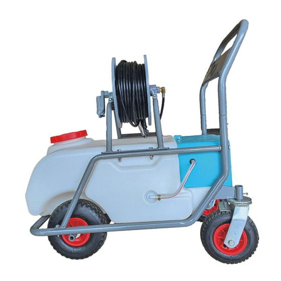
Page 6: Structure Diagram
STRUCTURE DIAGRAM SpecificationSTRUCTURE № Parts name № Parts name Frame Switch Wheels Voltmeter Tube Reel Charger Socket Water Tank Pressure Regulating Knob Water Tank Cover Battery Compartment Water Inlet Pipe COMPONENTS - 4 -... - Page 7 A Frame+Water Tank(x1) B Front Wheels(x2) C Rear Wheels(x2) D Wheel Axle(x1) E R-pin(x2) F Cap Nut(x8) G Bolts M8x35(x4) H Bolts M6(x2) I Flat Pad(x4) J Tube Reel(x1) K Fixed Base(x2) L Crank Handle(x1) M Hose(x1) - 5 -...
-
Page 8: Assembly And Use
N Support Frame(x1) O Handrail(x1) P Bolts M8x40(x4) ASSEMBLY AND USE Step 1: Remove the brackets on both sides of the frame and take out the water tank. - 6 -... - Page 9 Step 2: Put the axle through the shaft sleeve (a), put in a gasket and a front wheel (b), then put 2 shims, 1 front wheel and 1 shim in sequence(c+d). Finally, pass through the opposite shaft sleeve, and then put two R-shaped pins into two holes between the front wheels to fix them(e). Step 3: Install the two universal wheels into the rear wheel (pay attention to the holes of the universal wheels), and fix them with M6 bolts.
- Page 10 Fix the support frame(N) with M8x35 bolts(F+G). Step5: Fix the fixed base with bolt M8x40(F+P)and install the tube reel. Step6: Step 7: Install the crank handle on the tube reel (near the front wheel side) and fix the screws on the shaft.
- Page 11 Step 9: Install the handle, spray bar, and proper nozzle in turn. Note: 1.A sealing ring shall be added at the connection between the water outlet and the handle. 2. If water leaks, please check whether sealing rings are added and tightened. Step 10: Install the pressure regulating knob(Press in by hand).
- Page 12 Step 14: Instructions A. Turn on the switch. ("1" means to turn on the power, and "0" means to turn off the power) B.Description of the voltmeter: Yellow Light "L": The battery is insufficient and needs to be charged. Green Light "N": Sufficient power, can be used normally. Red Light "H": Abnormal.
- Page 13 INTRODUCTION AND APPLICATION OF NOZZLE Model KF-01D KF-26E KF-04D KF-86E Picture Three-end Single-head copper Three-end copper Single-head plastic plastic nozzle: nozzle: provide a small nozzle: provide a Function nozzle: provide a small provide a large amount of spray, or linear large amount of introduction amount of spray, or...
- Page 14 The pressure knob must be adjusted to avoid intermittent operation of the motor pump Note when using. (It is normal if the indicator light does not flash or the motor pump works continuously.) - 12 -...
- Page 15 INTRODUCTION AND APPLICATION OF NOZZLE Problem Reasons Solution The motor does The power connection wire falls off Check the connecting wire and plug the connector not start after the Battery is dead Use after charging power is turned The power switch is off Switch on The motor makes The fixing screws of the water...
- Page 16 Open the battery cover, take out the battery, and replace it with a good one. The black wire is connected to the "-" The battery is broken (the charger pole, and the red wire is connected to the "+" pole. (Note: indicator is green, but the spray Before removing the battery, please take a picture of the cannot be used)
- Page 17 Manufacturer: TAIZHOU KAIFENG PLASTIC&STEEL CO., LTD. ADD: NO.819 SOUTH ROAD OF JIUTANG, SANJIA JIAOJIANG DISTRICT, TAIZHOU, ZHEJIANG, CHINA MADE IN CHINA...
- Page 18 E-mail: CustomerService@vevor.com...
Need help?
Do you have a question about the KF-60C-1 and is the answer not in the manual?
Questions and answers
Where is the power connecting wire
The power connecting wire for the VEVOR KF-60C-1 is inside the battery compartment. The black wire connects to the "-" pole, and the red wire connects to the "+" pole of the battery.
This answer is automatically generated
purchased model KF-60C-1 and pump has crack in housing need part number for replacement pump
The part number for a replacement pump for the VEVOR KF-60C-1 model is not provided in the context.
This answer is automatically generated