Advertisement
INTRODUCTION
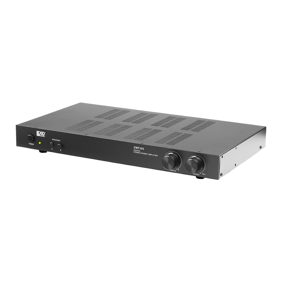
Congratulations on your purchase of the OSD Audio XMP300. Please take a few moments to read this entire manual, and be sure to retain this document for future reference. Please read and observe all safety instructions detailed.
 NOTE: If any partof this product is damaged or missing, please call your dealer or OSD Audio directly at 562-697-2600.
Please read your warranty and retain your receipt and original carton for possible future use.
For more information aboutoSD Audio electronics, speakers and accessories please visit www.osdaudio.com
FEATURES
- MAIN / INTERRUPT priority input switching
- MAIN auxiliary output
- Speaker A/B switching
- Front panel Balance and Volume controls
- Signal sensing "Power On" and Trigger mode
- Rear mounted treble and bass controls
SPECIFICATIONS
| Stereo (8 ohm): | 150W x 2, <1% THD+N |
| Stereo (4 ohm): | 300W x 2, <1% THD+N |
| Bridged Mono (8 ohm): | 450W, 1kHz, <1% THD+N |
| Frequency Response: | 10Hz ~ 30kHz, -2dB/ +1dB |
| Signal to Noise Ratio: | 100dB below 150W output into 8 ohms w/20kHz Lowpass filter |
| Channel Separation: | 65dB @ 1kHz, referred to 150W output into 8 ohms |
| Input Sensitivity: | 700mV input for rated 150W output into 8 ohms |
| Bass/Treble Control: | +/- 12dB @ 100Hz and 10kHz |
| AC Power Consumption: | 450W maximum |
| Net Weight: | 7.9lbs / 3.7kgs |
| Gross Weight: | 10.7lbs / 5kgs |
DIMENSIONS

IMPORTANT SAFETY INSTRUCTIONS

RISK OF ELECTRICAL SHOCK DO NOT OPEN
TO REDUCE THE RISK OF ELECTRIC SHOCK, DO NOT REMOVE THE COVER. NO USER SERVICABLE PARTS INSIDE. REFER SERVICING TO QUALIFIED PERSONNEL!
EXPLANATION OF SAFETY SYMBOLS
The exclamation point within an equi lateral triangle is intended to alert the user of the pr esence of importantoperating and maintenance (servicing) instructions in the literatur e accompanying the appliance.
 The lightning flash with the arr owhead symbol within an equilateral triangle is intended to alert the user to the pr esence of uninsulated "dange ro us voltage" within the products' enclosure that may be of sufficient magnitude to constitute a risk of electric shock to persons.

TO PREVENT FIRE OR SHOCK HAZARD, DO NOT EXPOSE THIS APPLIANCE TO RAIN OR MOISTURE. THEAPPARATUS SHALL NOT BE EXPOSED TO DRIPPING OR SPLASHING AND THAT OBJECTS FILLED WITH LIQUIDS, SUCH AS VASES, SHALL NOT BE PLACED ON APP ARATUS.

TO PREVENT FIRE OF SHOCK HAZARD, DO NOT USE THIS PLUG WITH AN EXTENSION CORD, RECEPTACLE OR OTHER OUTLET UNLESS THE BLADES CAN BE FULL Y INSERTED TO PREVENT BLADE EXPOSURE.
THE MAINS PLUG IS USED AS DISCONNECT DEVICE. THE DISCONNECT DEVICE SHALL REMAIN READILY AVAILABLE.
ONLY USE ATTACHMENTS OR ACCESSORIES SPECIFIED OR PROVIDED BY THE MANUFACTURER.
- Read these instructions.
- Keep these instructions.
- Heed all warnings.
- Follow all instructions.
- Do not use this apparatus near water.
- Clean only with dry cloth.
- Do not block any ventilation openings. The ventilation should not be impeded by covering the ventilation openings with items such as newspaper, tablecloths, curtains etc. Install in accordance with the manufacturer's instructions.
- Do not install near heat sources such as radiators, heat registers, stoves, or other apparatus (including amplifiers) that produce heat. No open flame sources, such as lighted candles, should be placed on the apparatus.
- Do not defeat the safety purpose of the polarized or grounding type plug. A polarized plug has two blades with one wider than the other. A grounding type plug has two blades and a third grounding prong. The wide blade or third prong is provided for your safety. If the provided plug does not fit into your outlet, consult an electrician for replacementof the obsolete outlet.
- Protect the power cord from being walked on or pinched particularly at the plugs, convenience receptacles, and at the pointof exit from the apparatus.
- Only use attacheements/accessories specified by the manufacturer.
- Use only with the cart, stand, tripod, bracket, or table specified by the manufacturer, or sold with the apparatus. When a cartor rack is used, use caution when moving the cart/apparatus combination to avoid injury from tip-over.
- Unplug the apparatus during lightning storms or when unused for long periods of time.
- Refer all servicing to qualified personnel. Servicing is required when the apparatus has been damaged in any way, such as power supply cord or plug is damaged, liquid has been spilled or objects have fallen into the apparatus has been exposed to rain or moisture, does notoperate normally, or has been dropped.
![]()
To reduce the risk of fire or electric shock, do not expose this apparatus to rain or moisture. The apparatus shall not be exposed to dripping or splashing and thatobjects filled with liquids, such as vases, shall not be placed on apparatus.![]()
The mains plug/appliance coupler is used as disconnect device, the disconnect device shall remain readily operable.![]() This equipment is a Class II or double insulated electrical appliance. It is designed in such a way that it does not require a safety connection to electrical earth.
This equipment is a Class II or double insulated electrical appliance. It is designed in such a way that it does not require a safety connection to electrical earth.![]()
- This lightning flash with arrowhead symbol within an equilateral triangle is intended to alert the user to the presence of non-insulated "dangerous voltage" within the product's enclosure that may be of sufficient magnitude to constitute a risk of electric shock.
![]()
to reduce the risk of electric shock, do not remove cover (or back) as there are no user-serviceable parts inside. Refer servicing to qualified personnel.- The exclamation point within an equilateral triangle is intended to alert the user to the presence of importantoperating and maintenance instructions in the literature accompanying the appliance.
 This equipment is a Class II or double insulated electrical appliance. It is designed in such a way that it does not require a safety connection to electrical earth.
MAGNETIC FIELD:

Do not locate sensitive high-gain equipment such as preamplifiers or tape decks dir ectly above or below the unit. Because this amplifier has a high power density, it has a strong magnetic field, which can induce hum into unshielded devices that are located nearby. The field is strongest just above and below the unit. If an equipment rack is used, we recommend locating the amplifier(s) in the bottom of the rack and the preamplifier or other sensitive equipment at the top.
FRONT PANEL CONTROLS

Figure 1. Front Panel
- Power Switch
Switches the XMP300 on or of f. A red LED indicates connection to AC power while in standby mode. Turns green indicating audio signal is present.
- Speaker Selector
Selects speaker zone A or B. For A + B zones push both buttons in.
- Balance
Fades speaker output between the Right and Left Channels
- Volume
Adjusts amplifier volume.
REAR PANEL CONTROLS

Figure 2. Rear Panel
- Bass and Treble Controls
These controls can adjust bass and treble frequencies +/- 12dB at 100Hz and 10kHz.
- Interupting Line Input
This is the secondary input, use MAIN IN for your main input.
INTERRUPTING INPUT can be used if a second source is desired and takes over when signal is present and has at least a 5mV level. When there is no signal, or a signal with less than 5mV level, the amp switches back to MAIN IN after a brief delay.
- Main Input/Output
MAIN IN should be used as the "primary" or main input for the amplifier. Connect your receiver or main source to this input. Use MAIN OUT to pass MAIN IN signal to another amplifier.
- 12V Trigger
Allows the XMP300 to be powered on by other electronics or to power onother electronics via a 3.5mm mini phone plug cable.
- Mode Select Switch
Switches the amplifier from Stereo mode to Bridged mode.
STEREO MODE
If you will be connecting one or two pair of speakers to the amplifier, place the switch in the "Stereo" position.
![warning]() NOTE: For playing 2 pairs of speakers (A plus B), make sure each speaker has an impedance of 8 ohms or greater.
NOTE: For playing 2 pairs of speakers (A plus B), make sure each speaker has an impedance of 8 ohms or greater.
BRIDGED MODE When set to "Bridged" mode, the amplifier is a single channel mono amplifier.
BRIDGED MODE- MONO APPLICATION
For bridged mode, playing Right and Left together as mono output, plug RCA cables in to Right and Left RCA at MAIN input. Set the MODE switch to BRIDGED and follow the instructions for bridged speaker connection in the SPEAKER TERMINALS section of this manual.
![warning]() NOTE: The XMP300 supplies 450W in bridged mode, Please verify that your speakers are capable of handling such power to avoid possible damage!
NOTE: The XMP300 supplies 450W in bridged mode, Please verify that your speakers are capable of handling such power to avoid possible damage!
- AUTO ON Select Switch
Power can be turned on and off manually via the switch on the front panel or automatically by signal sensing. Set it to NORMAL for manual power on/off. Set to AUTofor signal sensing; the amp will turn on when audio signal is detected at the inputs.
![warning]() NOTE: The front panel power switch must be in the ON position (pushed in) for the AUTO ON feature to operate.
NOTE: The front panel power switch must be in the ON position (pushed in) for the AUTO ON feature to operate.
- Speaker Zone A Output
Speaker output terminals for zone A. Minimum impedance: 8 ohm bridged or 4 ohm stereo.
- Speaker Zone B Output
Speaker output terminals for zone B. Minimum impedance: 8 ohm bridged or 4 ohm stereo.
SPEAKER TERMINALS - STEREO MODE
For stereo output connect the speaker's positive (red) terminal to the amplifier's positive (red) terminal, and the speaker's negative (black) terminal to the amplifier's negative (black) terminal for each Right and Left speaker.
SPEAKER TERMINALS - BRIDGED MODE
Place the "MODE" switch in the "BRIDGED" position and use both red terminals to connect to the speaker. Connect the speaker's positive (red) terminal to the amplifier's red (+) terminal noted next to the bridging mark, and the speaker's negative (black) terminal to the amplifier's unmarked positive (red) terminal.
![warning]() NOTE: Only one zone (A or B) can be bridged. Do not attempt to bridge both A and B speaker terminals! This may result in a lower impedance than the amplifier is designed for and may damage your amplifier. The minimum impedance for the total load connected in bridged mode is 8 ohms.
NOTE: Only one zone (A or B) can be bridged. Do not attempt to bridge both A and B speaker terminals! This may result in a lower impedance than the amplifier is designed for and may damage your amplifier. The minimum impedance for the total load connected in bridged mode is 8 ohms.
![warning]() NOTE: Use Class 2 wiring for speaker connections. To wire the output connector:
NOTE: Use Class 2 wiring for speaker connections. To wire the output connector: - Strip the insulation off each speaker wire to expose 3/8" (10 mm) of bare conductor.
- Unscrew the output terminal binding post several twists, insert each wire into the correct terminal.
- Tighten binding post by twisting clock-wise until it is firmly clamping the speaker wire.
![]()
While the amplifier does self-protect under most improper output conditions, misconfiguration of loudspeaker mode and incorrect connection of loudspeakers could damage connected loudspeakers and/or amplifier. Please refer installation to a qualified installation professional, and always check state and local electrical codes when installing.
![warning]() NOTE: To prevent sonic degradation in your speaker installation, total speaker wire resistance should be kept below 0.5 ohms. This table lists recommended speaker wire gauge versus wire run length.
NOTE: To prevent sonic degradation in your speaker installation, total speaker wire resistance should be kept below 0.5 ohms. This table lists recommended speaker wire gauge versus wire run length.
50' or less - 16 Gauge 2-Cond. CL3 Rated
50' - 150' - 12 Gauge 2-Cond. CL3 Rated
150' - 200' - 10 Gauge 2-Cond. CL3 Rated
- Power Cord
This amplifier is configured for operation at 115V (North America). A fuse located internally protection from fault conditions. Refer to qualified service personel should this need to be replaced.
APPLICATIONS
STEREO SETUP
In this configuration, the mode switch is set to "Stereo". Connect the line out jacks from a stereo pre-amplifier or source to the MAIN input jacks of your XMP300. Next connect your speakers to the terminals marked "Speaker A" observing proper polarity. Select the "A" speakers using the front panel zone selection buttons. Connect a second (optional) pair of speakers to the terminals marked "Speaker B". If you are connecting 4 speakers to the XMP300 they must be 8 ohm speakers only. Press A and B together to use both zones.

(From Pre-amp or Receiver Line Out)
SETUP FOR MULTIPLE SOURCE
In the multiple source set up, a distributed audio system is connected to the XMP300 as a local zone amplifier via the MAIN inputs. Normally the distributed audio system will be the audio source for the XMP300 The distributed audio is then passed on to be used by additional zones or sub zones in the distributed system via the MAIN outputs.

(From Local Source Line Out) (From Pre-amp Line Out) (Out to Additional Zones)
The audio outputof a local source, such as an MP3 Player, CD, television, computer, etc., is connected to the XMP300 via the INTERRUPTING inputs, and whenever the local source is active its signal will take priority over the distributed audio signal present at MAIN input. However, the distributed audio signal will still be present at the MAIN input. In this circumstance the audio outputof the local source will be heard via the XMP300. Once the local source is turned off or muted, the XMP300 will automatically switch back to the distributed audio system as an audio source, assuming the local source remains inactive. There is a delay of up to 6 seconds when switching from INTERRUPTING input back to MAIN inputs.
Limited Warranty
OSD Audio warrants its amplifier products against defects in materials and workmanship for a limited period of time. For a period of two years from date of original pur chase, we will repair or replace the product, atour option, without charge for parts and labor. Customer must pay all parts and labor char ges after the limited warranty period expires. The limited warranty period for factory refurbished products expires after ninety (90) days from date of original purchase.
This limited warranty applies only to purchases from authorized OSD Audio electr onics retailers. This limited warranty is extended only to the original purchaser and is valid only to consumers in the United States.
Consumers are required to provide a copy of the original sales invoice from an authorized OSD Audio dealer when making a claim against this limited warranty. This limited warranty only covers failur es due to defects in materials or workmanship thatoccur during normal use. It does not cover failures resulting from accident, misuse, abuse, neglect, mishandling, misapplication, alteration, faulty installation, modification, service by anyone other than OSD Audio, or damage that is attributable to Acts of God. It does not cover costs of transportation to OSD Audio or damage in transit. The customer should return his defective product, freight prepaid and insured, to OsdAudio ® only after receiving a Return Authorization.
This warranty will become void if the serial number identification has been wholly or partially removed, altered or erased. Repair or replacement under the terms of this warranty does not extend the terms of this warranty. Should a product prove to be defective in workmanship or material, the consumer 's sole remedies will be repair or replacement as provided under the terms of this warranty. Under no circumstances shall OSD Audio be liable for loss or damage, direct, consequential or incidental, arising outof the use of or inability to use the product. Ther eare no express warranties other than described above.
775 Columbia St., Brea. CA92821
www.osdaudio.com

Documents / Resources
References
Download manual
Here you can download full pdf version of manual, it may contain additional safety instructions, warranty information, FCC rules, etc.
Advertisement


Need help?
Do you have a question about the XMP300 and is the answer not in the manual?
Questions and answers