Advertisement
INTRODUCTION
We at OSD Audio thank you for your purchase of our XPA-1000/XPA-600 featuring Energy Efficient Class D Pure 70/100 Volt Commercial Power Amplifiers.
Both these Power Amplifiers are a welcome addition to our 70/100 Volt Lineup. A perfect add on to our current PAM245 or as a stand alone product both Amplifiers deliver 2 Channels of pure 70/100V power. In addition to the great features you've come to expect in an OSD Audio Amplifier, the XPA Amplifiers feature both Unbalanced and Balanced Line Inputs, an included IR-Remote Control, hard-wired IR Receiver module/sensor, an RS232 input for integration with control systems in a compact 1U rack Chassis. The Class D Power Supplies are 93% Efficient.
Don't let their compact size fool you, both amplifiers double down, the XPA-1000 is 2 x 500 Watts and the XPA 600 is 2 x 300 Watts
Inside the box:
One 70/100Volt Power Amplifier
One Product Manual
One IR Remote Control/
One IR Receiver Module Sensor Kit
One set of rack mounting hardware including two (2) brackets
AC Power Cord
SAFETY

TO REDUCE THE RISK OF ELECTRIC SHOCK,
DO NOT REMOVE COVER (OR BACK)
NO USER-SERVICEABLE PARTS INSIDE
REFER SERVICE TO QUALIFIED SERVICE PERSONNEL
 The lightning flash with arrowhead symbol within an equilateral triangle is intended to alert the user to the presence of un-insulated "danger- ous voltage" within the product's enclosure that may be of sufficient magnitude to constitute a risk of electric shock.
 The exclamation point within an equilateral triangle is intended to alert the user to the presence of important operating and maintenance (servicing) instructions in the literature accompanying the appliance.


TO REDUCE THE RISK OF FIRE OR ELECTRIC SHOCK,DO NOT EXPOSE THIS APPLIANCE TO RAIN OR MOISTURE.
This product was designed and manufactured to meet strict quality and safety standards. There are, however, some installation and operation precautions, which you should be particularly aware of.
- Read Instructions - All the safety and operating instructions should be read before the appliance is operated.
- Retain Instructions - The safety and operating instructions should be retained for future reference.
- Heed Warnings - All warnings on appliance and in the operating instructions should be adhered to.
- Follow instructions - All operating and use instructions should be followed.
- Water and Moisture - The appliance should not be used near water - for example, near a bathtub, washbowl, kitchen sink, laundry tub, in a wet basement, or near a swimming pool, etc.
- Carts and Stands - The appliance should be only with a cart or stand that is recommended by the manufacturer. An appliance and cart combination should be moved with care. Quick stops, excessive force, and uneven surfaces may cause the appliance and cart combination to overturn.
![]()
- Wall or Ceiling Mounting – The appliance should be mounted to wall or ceiling only as recommended by the manufacturer.
- Ventilation – The appliance should be situated so that its location or position does not interfere with its proper ventilation. For example, the appliance should not be situated on a bed, sofa, rug or similar surface that may block the ventilation openings; or, place in a built-in installation, such as a bookcase or cabinet that may impede the flow of air through the ventilation openings.
- Heat – Do not install near any heat sources such as radiators, heat registers, stoves, or other apparatus ( including amplifiers ) that produce heat.
- Power Sources – The appliance should be connected to a power supply only of the type described in the operation instructions or as marked on the appliance.
- Grounding or Polarization – Do not defeat the safety purpose of the polarized or grounding-type plug. A polarized plug has two blades with one wider than the other. A grounding type plug has two blades and a third grounding prong. The wide blade or the third grounding prong are provide for your safety. If the provided plug does not fit into your outlet, consult an electrician for replacement of the obsolete outlet.
- Power-Cord Protection – Power supply cords should be routed so that they are not likely to be walked on or pinched by items placed upon or against them, paying particular attention to cord at plugs, convenience receptacles, and the point where they exit from the appliance.
- Cleaning – Clean only with dry cloth.
- Power Lines – An outdoor antenna should be located away from the power lines.
- Nonuse Periods – The power cord of the appliance should be unplugged from the outlet when left unused for a long period of time.
- Accessories – Only use attachments/accessories specified by the manufacturer.
- Object and Liquid Entry – Care should be taken so that objects do not fall and liquids are not spilled into the enclosure through openings.
- Damage Requiring Service – The appliance should be serviced by qualified service Personnel when:
- The Power-supply cord or the plug has been damaged; or
- Objects have fallen, or liquid has spilled into the appliance; or
- The appliance has been exposed to rain; or
- The appliance does not appear to operate normally or exhibits a marked change in performance; or
- The appliance has been dropped, or the enclosure damaged.
- Servicing – The user should not attempt to service the appliance beyond that described in the operating instructions. All other servicing should be referred to qualified service personnel.

FEATURES & SPECIFICATIONS
| FEATURES | XPA1000 | XPA600 |
| Power Output | 500 Watts Per Channel | 300 Watts Per Channel |
| Design | Class D 93% Efficient | |
| Inputs | Balance and Unbalanced Inputs | |
| Outputs | Unbalanced Loop Line Output to Another Amplifier | |
| 12V Trigger | For Remote Turn On | |
| 12V Trigger | Out to Trigger External Device | |
| 70V/100V | Selectable Rear Panel Swit | |
| IR Remote | IR Remote Included/ Hard Wired IR Receiver/ Codes Availab | |
| RS232 | RS232 Querries & Commands Available | |
| Output Level Meter | Front Panel Status; Protection & Warning LEDs | |
| Chassis Design | 1U Rack | |
| Voltage | Multi-Voltage: AC115/230V | |
| SPECIFICATIONS | XPA1000 | XPA600 |
| Power Output | 500W X2 | 300 W X2 |
| THD | 1% (Rated Power) | |
| Signal To Noise | >90dB A Weighted | |
| Freq Response | 20Hz - 22kHz +0/-2dB | |
| Adjustable Level | Min - Max | |
| Line Level Input Sensitivity | 510mV | |
| Thermal Protection | Yes | |
| Short Protection | Yes | |
| Dimensions (WxHxD) | 435mm x 44mm x 240mm 17" x 1.7" x 9.4" | |
| Weight | 4.2Kgs / 9.25lbs | |
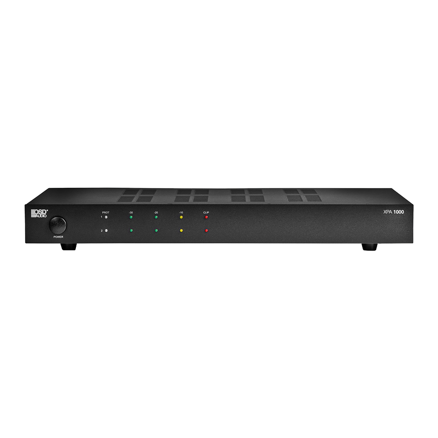
FRONT & REAR PANEL DESCRIPTION

- Power Switch
- Protection LED: Normal (Blue) Protection (Red)
- Output Level Meter: 3 LEDs for each channel -30, -20, -10 (Flashing Blue) Clip Indicator (Red Light) Illuminates when each channel clips.
NOTE: If clipping occurs trun the gain control down on the back of the amp.

- 70/100V Selector: 70V for U.S., 100V for Europe
- RS232 Control
- IR Receiver Connection
- 12V Trigger In & Out: Apply 4.5-15 Volts DC to turn Amplifier On, Link other equipment connected to the 12V Out with the same 12V signal.
- Audio Loop Outputs: RCA Connections, unbalanced mono for sending audio from channel one (1) to channel two (2) or output to other components.
- Unbalanced Inputs: Unbalanced mono RCA Source inputs for Channels One (1) and Two (2)
- Balanced Inputs Connector 3 & 4: Six Pin Set Screw connector for two Balanced Input Connections for Channels 3 and 4
- Output Gain Controls: Ch1 & Ch2 Level control knob for Channels 1 and 2. Turn clockwise to increase and counterclockwise to decrease output levels.
- Speaker Output Connector: Speaker output connector with set screw for Channels one (1) and two (2)
- Multi Voltage Selector Switch: 115V or 230V
- IEC Power Receptacle
- AC Fuse/Holder
REFERENCE INFORMATION
The following information is provided for reference only. Please consult a professional if unsure about any aspects of commercial or residential installations.
Speaker Connection
The rear panel of the amplifier contains 2 Line Outputs (Line 1 and Line 2). BE SURE TO CONNECT SPEAKERS PROPERLY, see line voltage instructions below. The speaker lines are to be connected directly between the appropriate COM terminal on the terminal strip and the terminal corresponding to the impedance of the speaker(s). Connect the cables to the terminals on the screw terminal strip provided. Use the screw terminals which correspond to the proper polarity of the speaker(s). One lead must always be connected to the COM.

When 70V constant line voltages are used, a line matching transformer must be used with each speaker. All transformers must be connected in parallel.
ALWAYS CONNECT LINE TRANSFORMERS IN PARALLEL, NEVER CONNECT IN SERIES
Speaker Impedances
Speaker terminal taps for 70V constant line voltage are provided on the rear panel of the unit. To connect the power output directly to a speaker or PA horn or a combination of speakers and/or PA horns, connect to the COM and (+) terminal on the strip. Be sure the speaker(s) or PA horn(s) can handle a reasonable power output from the amplifier or permanent damage to the speaker(s) or PA horn(s) may result. Also, be careful not to overload the amplifier with too many speakers or PA horns. If it is desired to use a number and variety of speakers, the speakers must be arranged in various series or parallel arrays to provide proper impedance matching. 70V constant line voltage must be used (parallel connection only). If you are not familiar with impedance matching, consult a professional installer or technician for advice. If 70V constant line voltages are used, a line matching transformer must be used with each speaker. Again do not overload or use incompatible speakers. Line transformers are the preferred method for multi-speaker installation.
Cable Requirements
Output cabling need not be shield in most case and should be of sufficient gauge to minimize losses due to the resistance of the wire over long runs (insertion loss). Cable thinner than 18 gauge AWG is not recommended. Long runs require 16 gauge AWG or heavier.
In some cases where the output cable is run in close proximity to unshielded intercom cables, electrical cables, radio transmission antennas or other sources of interference, or when the amplifier is being used for paging from a telephone system, the amplifier may require shielded output cabling to prevent audio feedback or interference.
WHENEVER IN DOUBT ABOUT INSTALLATION, CONSULT WITH A PROFESSIONAL INSTALLER OR TECHNICIAN. OTHERWISE, PERSONAL INJURY, DAMAGE TO THIS AMPLIFIER AND/OR SPEAKERS MAY RESULT AND YOUR WARRANTY MAY BE VOID.
FEATURES AND FUNCTION
Rack Mounting
The XPA-1000/600 both come with Rack Mounts in the box. Remove the two chassis screws from each side panel, closest to the front panel Attach the rack-mount ears to the sides of the front face plate using the screws that come with the rack mounts (2 each side). The amplifier will occupy 1U of rack space. Ensure that the unit is in a well-ventilated area that provides adequate cooling. Free air space is required above the amplifier and below the amplifier. The recommended distance is 1U to 2U, 1.75" to 3.5" being sure to avoid blocking any vents on the unit's chassis.

Bottom feet on the amplifier chassis may be removed if necessary.
NOTE: Do not place the screws back into the chassis. Without the feet, the length of the screw may touch internal components and affect the performance of the amplifier.
Balanced Input
Use the BALANCED INPUT to connect balanced or unbalanced cables to the amplifier.

NOTE: The unbalanced connection needs a jumper from the Shield to the Negative. The unbalanced connection is used when there is no balanced source and more additional connections to the amp are needed.
Unbalanced Connections
Use standard RCA cables to connect sources using the UNBALANCED LINE IN input. Connect sources through the applicable mono input. Use the LOOP OUT ports to connect more amplifiers or equipment.

Using Fixed Loop Out
The LOOP OUT connections on the amplifier may be used to send audio signals to other equipment, or to the other channel of the amplifier. This connection sends audio signals out from the UNBALANCED INPUT of the channel.

Connect Channel 1 Loop OUT to Channel 2 Loop in for two channels with one source, or to equipment.
APPLICATION DIAGRAMS
Single Source W/ Stereo Output

Two Source W/ Two Mono Output Zones

Single Mono Source Unbalanced

IR REMOTE CONTROL
XPA IR Remote
The XPA-1000 and XPA-600 IR Remote Controller, controls the individual zones on our PAM-1270 amplifier. It can also be used to teach IR commands to a programmable, integrated universal IR Remote, zone control system or other IR routing device.
Both of the XPA-1000 and the XPA-600 come with a IR Receiver module that connects to the IR two conductor input connector. There is no built in IR Sensor. The following are brief descriptions of each button. Universal IR codes are also available on the next page of the Owners Manual.

IR Remote Function

- IR LED - One, high-output IR LED. The IR LED flashes invisible (infrared light pulses that are the control codes for the XPA-1000 & XPA-600. The LED must be pointed at an IR receiver that is connected to an XPA-1000/600. The IR Receiver Sensor must be connected to the IR 2 Conductor Connector
- Power On/Off– Separate Power On (Red Button) and Power Off.
- Source Selects between the Unbalanced and Balanced Sources.
- Ch1 Vol+, Vol- & Mute – CH1-Unbalanced/CH3-Balanced; Volume Up. CH1-Unbalanced/CH3-Balanced and Mute for CH1 and CH3.
- Ch2 Vol+, Vol- & Mute – CH2-Unbalanced/CH4-Balanced; Volume Up. CH2-Unbalanced/CH4-Balanced and Mute for CH2 and CH4.
- All Channels Vol+, Vol- & Mute – All Channels-Unbalanced/ Balanced; Volume Up. All Channels-Unbalanced/Balanced and Mute for All Channels.
IR CODES & RS232 COMMANDS
XPA IR Remote Universal Codes
The XPA 70V Amplifiers IR Remote Controller, controls the individual Power On/Off, Source, and the Volume Levels for Channels 1/3 & 2/4 and All Channels combined. It can also be used to teach IR commands to a programmable, integrated universal IR Remote or other IR routing device. The following are the Remote Controller Head Code and Hex codes for the individual buttons:

| XPA1000/XPA600 Remote Controller Head Code: 00FF | |||
| Function Key | Keys | Code | Remark |
| Power On | K1 | 45 | power turn amplifier on |
| Power Off | K2 | 47 | power turn amplifier off |
| Source | K3 | 43 | RCA Balance/UnBalanced Inpus select |
| CH1 VOL + | K4 | 16 | CH1/CH3 VOL UP |
| CH1 VOL - | K5 | 19 | CH1/CH3 VOL DOWN |
| MUTE | K6 | OD | CH1/CH3 Silence audio on amp |
| CH2 Vol + | K7 | OC | CH2/CH34 VOL UP |
| CH2 Vol - | K8 | 18 | CH2/CH34 VOL DOWN |
| MUTE | K9 | 5E | CH2/CH4 Silence audio on amp |
| All VOL + | K10 | O8 | CH1+CH2 and CH3/CH4 VOL UP |
| All VOL - | K11 | 1C | CH1+CH2 and CH3/CH4 VOL DOWN |
| MUTE | K12 | 5A | CH1+CH2 and CH3+CH4 Silence audio on amp |
| XPA1000/XPA600 RS232 Commands | |||
| Sequence # | Name | Command | Remark |
| 1 | <CR>: | Enter Key | |
| 2 | <Esc>: | Escape Key | |
| 3 | <Spaec>: | Space Key | |
| 4 | Nov<CR> | Show All PA Status: | |
| 5 | Power<Space>On<CR> | Power On | Power On/Off Control: |
| 6 | Power<Space>Off<CR> | Power Off | Power On/Off Control: |
| 7 | Power<Space>Toggle<CR> | Power Toggle Control | Power On/Off Control |
| 8 | Source<Space>1<CR> | RCA (Unbalanced Inputs) | Source Control: |
| 9 | Source<Space>2<CR> | Balanced Inputs | Source Control: |
| 10 | Volume<Space>xx<CR> | Volume xx (xx range 00-63) | Total Volume Control: 00 to MIN; 63 to MAX |
| 11 | Volume<Space>01<CR> | Setting Volume as 01 level | Total Volume Control |
| 12 | Mute<Space> On<CR> | Mute On RCA (Unbalanced/balanced inputs) | Mute Control |
| 13 | Mute<Space>Off<CR> | Mute Off RCA (Unbalanced/balanced inputs) | Mute Control |
| 14 | Mute<Space>Toggle<CR> | Mute Toggle Control | Mute On/Off Control |
| 15 | Ch1 Mute On/Off/Toggle | Ch1 Mute On/Ch1 Mute Off/Ch1 Toggle | Ch1/Ch3 Mute Control |
| 16 | Ch2 Mute On/Off/Toggle | Ch2 Mute On/Ch2 Mute Off/Ch2 Toggle | Ch2/Ch4 Mute Control |
| 17 | Attenuator xx(00-31) | Ch1 Ch2 Vol | Total Attenuator |
| 18 | Ch1 Attenuator xx(00-31) | Ch1 Vol(xx range 00-31) | Ch1 Volume Attenuator |
| 19 | Ch2 Attenuator xx(00-31) | Ch2 Vol(xx range 00-31) | Ch2 Volume Attenuator |
| 20 | Save<CR> | Store all current setting w/out power on/off status | |

Documents / ResourcesDownload manual
Here you can download full pdf version of manual, it may contain additional safety instructions, warranty information, FCC rules, etc.
Download OSD XPA-1000, XPA-600 - Commercial Amplifier Manual
Advertisement


Need help?
Do you have a question about the XPA-1000 and is the answer not in the manual?
Questions and answers