OSD NERO MAX 12, MAX 8, CONTROL 12 - Multi-Room Amplifier Manual
- Manual (22 pages) ,
- Owner's manual (11 pages) ,
- Manual (4 pages)
Advertisement
IMPORTANT SAFETY PRECAUTIONS
This manual contains important instructions for the safe operation of the unit. Read and follow the safety instructions and all other instructions. Keep the manual for future reference. Make sure that it is available to all those using the device. If you sell the unit, please make sure that the buyer also receives this manual.
- Use only an approved power cable and plug or distribution board to connect your amplifier to a power outlet. Do not use an extension cable.
- Never touch the mains plug if your hands are wet.
- Do not attempt to open the equipment. Refer servicing and repair to qualified service personnel. Touching live components inside the case can result in a fatal electrical shock!
- Read the Owner's Manual and Safety Precautions before operating the equipment.
- Keep this Manual in a safe place so that you can refer to it later.
- Please heed all warnings on the equipment itself and in the Owner's Manual.
- Please follow the instructions contained in your Owner's manual and never use this equipment for any purpose other than is explained in this Owner's Manual.
- Only connect this equipment to a power source of the type described in the Owner's Manual and specified for this equipment.
- Make sure that there is adequate ventilation around the equipment to allow proper cooling. Keep the equipment away from direct sunlight. Avoid installing the unit close to sources of heat or in spaces such as bookshelves or cupboards where heat radiation may be obstructed. Avoid excessive temperatures in the room, as these could ultimately damage sensitive components and reduce the service life of your player.
- Never use the unit in damp rooms, at temperatures of below 15°C, or in the open air. When bringing your amplifier in from the cold, allow it time to achieve room temperature before plugging it in.
- Always switch the unit off before removing or inserting interconnects. Doing this with the amplifier switched on can damage not only the amplifier itself but also equipment connected to it.
- If you ever spill water or any other liquid onto the equipment: Do not touch the case! Remove the plug from the wall outlet and contact your dealer or our service department.
- Never remove the earth connection from the plug. It is there to ensure your safety.
- Arrange the power cable so that no one can accidentally stand on it. Avoid locating it under objects that might put pressure on the cable. Pay particular attention to areas where the cable exits from plugs, AC outlets and from the unit itself.
- Never operate the unit without being present. Disconnect the plug from the wall outlet and remove all aerial connections (including cable aerials) when: you clean the unit, you do not expect to use the unit for long periods of time, during an electrical storm.
- If you have an external antenna or cable antenna connected to your hi-fi system, we recommend that you use a signal isolating filter to avoid interference or damage during thunderstorms.
- Problems: If you lose the sound while the amplifier is operating, or if you notice smoke or burning, switch the unit off immediately and contact your dealer or our service department.
- Only replace defective fuses after you have traced and removed the cause of the fault and then only with a fuse of the same rating. Remove the mains plug before changing fuses. Use an insulated screwdriver to remove and replace the fuse.

You are cautioned that any changes or modifications not expressly approved in this manual could void your authority to operate this equipment. Properly shielded and grounded cables and connectors must be used for connection to host computers and/or peripherals in order to meet FCC emission limits. To reduce the risk of electric shock, the speaker cable should be connected to the apparatus and the speakers in accordance with the following instructions.
DO NOT defeat the safety purpose of a grounding or polarized plug by removing ground pins or using unsafe adapters. A polarized plug has two blades - one wider than the other. A grounding plug has a third ground prong in addition to the two main conductors. The wide blade or third grounding prong is provided for your safety. If the provided plug does not fit your outlet, consult an electrician to replace your obsolete outlet. If you replace the power cord, only use one of similar type and equal or greater current rating.

For Class II apparatus only: This symbol means that the equipment is a Class II or double insulated electrical appliance. It has been designed in such a way that it does not require a safety connection to electrical earth. When servicing use only identical replacement parts installed by an instructed person or with use of ready-made leads or cords.
WARNING SYMBOLS
 TYPE OF DANGER: Warning - Danger Zone
 TYPE OF DANGER: Warning - High Voltage

Hazardous Voltage
Hazardous voltage may be present at cable ends and screw terminals. The connection of screw terminals as well as all maintenance and repair work on the electrical installation of the device must only be performed by qualified electrical personnel in volt-free-condition. Failure to do so may result in electric shock and risk of fire and loss of life.
By all means you have to observe all electrical safety instructions applicable at the place of operation.
Electric shock caused by short-circuit
Always use proper ready-made insulated mains cabling (power cord) with a protective contact plug. Do not modify the mains cable or plug. Failure to do so could result in electric shock/death or fire. If in doubt, seek advice from a registered electrician.
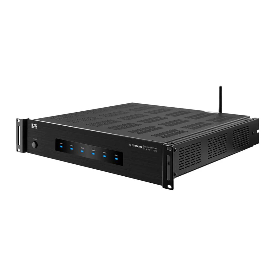
INTRODUCTION
The NERO MAX12, MAX8 and CONTROL12 are functional, easy to install, highly compatible, expandable, and user-friendly audio distribution systems. They feature 6 Analog Source Inputs, the MAX12 and MAX8 providing up to 80W @4-ohm from a Class D amplifier for 6 or 4 zones - expandable to 18 zones, which can be controlled by the either the OSD Control App (Free App that Duplicates the Keypads), Optional Keypads with IR Remote Control or RS-232.
The CONTROL12 offers the same 6 sources with pre-amp outputs only. Allowing for integration with alternative, more powerful, amps such as the MX Series.
FEATURES
- 6x6 or 6x4 Audio Matrix Switch and 6 Source Inputs.
- MAX12 and MAX8 have 6 or 4 Stereo, Bridgeable, amplified speaker outputs.
- Expandable to 2 or 3 units, giving 8/10/12/16/ and 18 stereo zones of distributed Audio.
- Free iOS & Android App (2.4GHz wireless networks only) duplicates the Control Panels for each Zone/Room. Optional Control Pads/IR Remote are available as well.
- High Efficiency Class D Amplifier (MAX12 & MAX 8); 80 watts (4-ohms) and 40 watts (8-ohms) Each Zone can drive a single 4-ohm pair of speakers or two pair of 8-ohm speakers, Stereo or Bridged Mono Output for combining ones for 100 Watts at 8 ohms (single 8-Ohm speaker per channel only)
- 3 Stereo line-level Pre-AMP L&R RCA Outputs (Zones 1-3) – MAX12 & MAX8 only
- 6 Stereo line-level Pre-AMP L&R RCA Outputs (Zones 1-6) – CONTROL12 only
- 4 Stereo line-level L&R RCA Analog Source Inputs, 1 Mini 3.5 mm Stereo Analog input, 1 auto-selecting Optical or Mini 3.5 Analog
- Optional keypads have a built-in IR receiver & IR remote controller for Source select/Volume/Treble/Bass.
- RS232 for transferring and receiving the serial data for control systems.
- 6 Individual Zone Status (3.5mm): Used to control external Zone Devices (12V triggers)
- 6 IR Emitter 3.5mm Mono RCA outputs + 1 IR Emitter/Blaster 3.5mm Mono Jack (MAX12 and MAX8 only), CONTROL12 - 2 IR Emitter 3.5mm Mono RCA outputs + 1 IR Emitter/Blaster 3.5mm Mono Jack
- Front panel LEDs for 6/4 zones indicating Power On, Standby and Mute.
- 1 PA Input jack to set all zones to Source 1 (12Vdc Trigger)
- External Mute In/Control Out (3.5mm Mono Jack RCA connections/12Vdc)
- AGC (Automatic Gain Control): brings low input levels up to a present-level
- Unit ID Selector Switch: Master/Slave 1/Slave 2(Expandable settings)
- Multi Voltage Selector 115V or 230V, AC Input connection with Fuse Receptacle (CE Certified)
SPECS
Power: (MAX12 and MAX8 only):
8 Ohm - 40W x 2 per zone 4 Ohm - 80W x 2 per zone
Bridgeable: 8 Ohm Only - 80W
S/N: MAX12 and MAX8 - >85dB A WTD
S/N: CONTROL12 -110dB
THD: MAX12 and MAX8 - <0.1%
THD: CONTROL12 – 0.05% (0.5dB)
Freq Response: 20Hz-20KHz
Input Impedance: >47 K Ohm
Output Impedance (line level) 100 Ohms
Input Sensitivity: 250mv
Protection: Overload, Short Circuit, Temperature
System Voltage: DC +12V
External Mute and TRIGGER OUT Voltage: DC +12V
Network Connector: RJ45, Standard 10/100Mb
Power Supply: AC 115V/60Hz - 230V/50Hz (CONTROL12 DC 15V/1.6A)
Output Connection: Terminal Block
Dimensions: 16.9" W x 3.5" H x 16.4" D (MAX12 and MAX8)
16.9" W x 1.75" H x 16.4" D (Control12)
Weight: MAX12 25lbs, MAX8 19lbs, Control12 4.5lbs
CONTENTS
- NERO MAX12 Amp or MAX8 or Control12
- Expansion Ribbon Cable
- Rack Ears
- Speaker Terminal Blocks (Pre-Installed on Amp)
- AC Power Cable
- Product Manual
FRONT/REAR PANEL
MAX12

- Power ON/OFF/ STANDBY
Depress the power button to turn on the system. Press it again to release the latch and power the unit off.
Note: Even if the power is on, each zone will remain in Standby mode until the zone is activated by command from either OSD Control App, keypad, or RS232. - Standby/Zone ON LED
These 6 LEDs illuminate to indicate the status of each zone.
Blue: In Standby mode.
White: In Activate mode.
Blue/White: In Mute mode.

- PRE-AMP OUTPUT x 3
Stereo Line level output for each zone. Connect to the inputs of amplifiers or powered speakers. - Bridge mode selector: See later sections for more details on using the Bridge mode.
- Speaker Outputs
- Ethernet Port
- Zone Status: Used to control external Zone Devices
- Source Inputs (Input 1/PA)
- IR Outputs to control Sources
-
- PA Trigger IN (Source 1)
- MUTE In/Control Out: This input can temporarily mute the system by connecting this unit to a relay closure switch on home automation system or phone system etc. When switch is on, it will short-circuit the input and mute the unit.
- Expansion IN/OUT Port: Connects up to 3 units total
- RS232 Port
- Voltage Selector (115V in US)
- AC Input
- Keypad Hub Input
- AGC (Automatic Gain Control): brings low input levels up to a preset-level
- Unit ID Switch
- RS232 or Ethernet control switch
- RESET: The RESET button is used to reset the ETHERNET back to factory default settings.
- ETHERNET/RS232 SWITCH: ETHERNET - When connecting the device via Ethernet to your Network. RS232 - When the device is controlled by PC or 3rd Party Control Device via RS-232 port.
MAX8

- Power ON/OFF/ STANDBY
Depress the power button to turn on the system. Press it again to release the latch and power the unit off.
Note: Even if the power is on, each zone will remain in Standby mode until the zone is activated by command from either OSD Control App, keypad, or RS232. - Standby/Zone ON LED
These 4 LEDs illuminate to indicate the status of each zone.
Blue: In Standby mode.
White: In Activate mode.
Blue/White: In Mute mode.

- PRE-AMP OUTPUT x 3
Stereo Line level output for each zone. Connect to the input of amplifiers or powered speakers. - Bridge mode selector: See later sections for more details on using the Bridge mode.
- Speaker Outputs
- Ethernet port
- Zone Status: Used to control external Zone Devices
- Source Inputs (Input 1/PA)
- IR Outputs to control Sources
-
- PA Trigger IN (Source 1)
- MUTE In/Control Out: This input can temporarily mute the system by connecting this unit to a relay closure switch on home automation system or phone system etc. When switch is on, it will short-circuit the input and mute the unit.
- Expansion IN/OUT Port: Connects up to 3 units total
- RS232 Port
- Voltage Selector (115V in US)
- AC Input
- Keypad Hub Input
- AGC (Automatic Gain Control): brings low input levels up to a preset-level
- Unit ID Switch
- RS232 or Ethernet control switch
- RESET The RESET button is used to reset the ETHERNET back to factory default settings.
- ETHERNET/RS232 SWITCH: ETHERNET - When connecting the device via Ethernet to your Network. RS232 - When the device is controlled by PC or 3rd Party Control Device via RS-232 port.
CONTROL12

- Power ON/OFF/ STANDBY
Depress the power button to turn on the system. Press it again to release the latch and power the unit off.
Note: Even if the power is on, each zone will remain in Standby mode until the zone is activated by command from either OSD Control App, keypad, or RS232. - Standby/Zone ON LED
These 6 LEDs illuminate to indicate the status of each zone.
Blue: In Standby mode.
White: In Activate mode.
Blue/White: In Mute mode.

- PRE-AMP OUTPUT
Stereo Line level output on each zone. Connect to the input of amplifiers or powered speakers. - SOURCE INPUTS Source1-3: RCA Stereo Input Source4-5: 3.5mm Stereo Input Source6: OPTICAL Digital Input
- TRIGGER OUTPUT When the zone is activated, the corresponding jack will output 12VDC to trigger another device.
- IR EMITTERS
- KEYPAD RJ-45 jack Connects to the keypad hub for up to 6 keypads.
- MASTER/SLAVE SWITCH Set the unit ID when connecting multi-Controller systems
- AGC Automatic Gain Control auto balances input level differences.
- ETHERNET/RS232 SWITCH
ETHERNET: When the amplifier connects to Ethernet. RS232: When the amplifier control by PC or Control Device via RS-232 port. - ETHERNET PORTS Dual LAN ports, one connects to the LAN port of local router. Another connects to network TV or another device which requires Ethernet.
- RESET The RESET button is used to reset the ETHERNET back to factory default settings.
- EXPANSION IN/OUT PORT
Expandable to 18 zones with 3 x Multi-zone Controller systems. - DC INPUT Connect the supplied DC adapter to the DC IN jack, and then plug it into a standard household outlet
KEYPADS
OPTIONAL KEYPAD (Sold Separately) as NERO-MAX12KEYPAD kit
Includes
- (6) MAX12 Keypads
- (1) MAX12 Keypad Hub
- (6) Outer Plates for Decora keypad inserts
- IR Remote Control (uses IR sensor in keypads to control amp, codes available from website)
- Product Manual

- Numeric LED Display
- IR Receiver Target
- Selection and Status LED's
- Power/Status. Press and Hold to turn Zone ON/OFF. When ON, press to toggle through settings
- Increase Volume, Treble or Bass
- Decrease Volume, Treble or Bass
- Source Select
REMOTE CONTROL

- POWER: Switches power (ON/OFF) for the certain zone.
- MUTE: Allows you to mute a certain zone.
- BALANCE: These L&R buttons can adjust the balance or L/R channel in stereo mode.
- VOLUME: Volume adjustment
- SOURCE: Used to select signal input.
- TREBLE: This allows you to increase or decrease the Treble level in an individual zone.
- BASS: This allows you to increase or decrease the Bass level in an individual zone.
CONNECTION
The Connect and Operate pages below refer to the MAX12. Both the MAX8 and Control12 connect and operate in the same way. The only difference being that the MAX8 only has 4 stereo zone outputs and the Control12 has no speaker outputs just pre-amp outs.
Connect & Operate
Before you begin to install the NERO MAX or CONTROL it is important to implement good installation practices:
- Make sure that AC power is disconnected before making ANY connections to the main unit and attached devices.
- Install in a well ventilated environment.
- Ensure any vents are not blocked to allow for proper circulation.
- Do not install above or below sources of heat.
- Use good quality cabling.
- The unit may be installed in a rack using the provided rack mount ears.
Connecting the Sources
Up to 6 dedicated sources can be connected to a single NERO MAX 12. Source 1-4 features Right and Left Female Unbalanced RCA Stereo Inputs (RCA Stereo Patch cords). Source 5 is 3.5mm Female input (Dual RCA to single Stereo 3.5mm adapter cable or 3.5mm to 3.5mm Stereo Aux cable) to RCA and Source 6 offers a choice of 3.5mm Stereo Input or Digital Fiber Optic Input (Optical Fiber Cable).

Note: Input 1 can be used as a global input for all zones when a source is connected to input 1 and the 12VDC is applied to the PA-IN (tip is positive) then source 1 will broadcast to all zones. If no 12VDC is applied, then the first input will be operating under normal conditions
Connecting Speakers
The NERO MAX12 & 8 can work with speakers that are 4-8 Ohm. There are two modes that can be set for different setups: Stereo or Bridged. An 8 Ohm speaker can only be used when in Bridged mode. To choose between modes, use the mode switch to determine modes for each zone (Number 2 Panel Descriptions)
Once you have properly identified the desired mode, strip about 1/4" of insulation and twist the copper strands. Connect the speaker wire to the screw down terminal as indicated on the amp. To loosen the terminal turn counterclockwise and to tighten the terminal turn clockwise. For better quality, we recommend used 12-14 AWG stranded copper speaker wire.

Using The Pre-Amp Outputs
There are 3 unbalanced, line level Pre-Amp outputs that correspond to the first 3 Outputs. These can be used to connect an additional amplifier, expand zones, or to connect a powered subwoofer. The Pre-Amp output levels are not fixed and are able to be controlled via OSD Control App, keypad, or RS232. Both pre-amp outputs and speaker out-puts work simultaneously, both the speaker-volume and the pre-amp output-level adjust volume at the same time.
Bridge Mode: There are 2 ways to configure the Bridge mode feature.
- To power a single speaker in a zone/room.
Convert your stereo signal into a mono signal using a product like our SMC21 (Stereo to Mono Convertor). Connect the mono RCA to the left RCA input for that zone, select Bridge YES. Connect a single 8 Ohm speaker in the zone/room. - To connect 2 speakers in a zone/room.
Connect the left and right RCA's to the left inputs of 2 zones/amp, link both zones in the OSD Control App (example: Living Room left and Living Room right), select Bridge YES and connect 2 8 Ohm speakers in the zone/room.
![]()

Connecting Optional Keypads
The Keypad kit comes with 6 POE enabled keypads. This allows for source control from each specific zone as well as IR routing to the appropriate source devices once selected. The Keypad kit also comes with a hub that allows for all 6-keypads to be connected to the amp via Cat5e/6.

Without power being connected, connect a Cat5e/6 cable to the RJ45 port labeled KEYPADS on the back of the NERO MAX/Control. We recommend terminating the Cat5e/6 using the 568B standard.

At this point it is also important to address your keypads. Refer to the chart below which is also found on the PCB board of the back of the keypad to set the dip switches according to the zone you would like it to control.

Connect the other end of the Cat5e/6 to the lone RJ45 port found on the front side of the Keypad Hub. Note that the Cat5e/6 between the unit and the hub should only be between 7-10ft in length. The RJ45 ports on the back of the Keypad Hub are not assigned but the single RJ45 port isolated on the bottom of the hub is reserved for cascading units.

Connect the other end of the terminated Cat5e/6 to the RJ45 port on the back of the assigned Keypad and installation is complete. Complete zone and source control as well as IR and power are provided through the single Cat5e/6.
Connecting and Using the Zone Status Ports
There are six 12V DC trigger outputs which correspond to the six output zones. When a zone is powered ON by the NERO MAX/Control keypad, the corresponding zone sends 12V DC to the trigger output jack. The triggers can be used to automatically switch peripheral equipment ON or OFF.

WIRING: 3.5mm Jack

Plug: Tip is Positive (+)
Trigger Outputs for Zones 1 - 6: Zone ON; 12V DC applied to the TRIGGER OUTPUT, Zone OFF; 12V DC removed from the TRIGGER OUTPUT.
Control

CONTROL: When any zone is on, 12V DC applied to the CONTROL OUT. When all Zones are OFF, 12V DC is removed from the CONTROL OUT.
TRIGGER INPUTS:
PA - IN: Apply 12V DC for input #1 override on all six zones.
EXT. MUTE - IN: Apply 12V DC to mute all zones
IR Emitters
When being used with Keypads, the NERO MAX / Control can receive IR signals from each zone, and routed back through the Cat5e/6 and Keypad up to the Amplifier to control the selected source. For example, if Source 2 - DVD is selected in Zone 1, the user will be able to control the DVD player to power the device ON/OFF, change settings etc.. Since the amplifier has discreet routing, ONLY the Source that is selected on each zone can be controlled. This prevents other sources from being accidentally controlled when selected on other zones.

Cascading Sources Into Additional Zones
The NERO MAX / Control can allow 6 sources to be distributed to up to 18 Zones on 3 different units using the provided ribbon cable to connect between units. To do this, first each unit needs to be addressed accordingly using the MASTER/ SLAVE Switch. there are 3 positions for this, Master, Slave 1 & Slave 2 which help identify each unit.

Once each unit is correctly addressed, use the provided expansion ribbon cables to connect the OUTPUT of the original MASTER unit into the INPUT of SLAVE 1. To cascade the sources into a third unit, using the provided expansion ribbon cable, go to the OUTPUT port from the device addressed as SLAVE 1 into the INPUT port of the device addressed as SLAVE 2.
APP CONTROL
Configuring Wireless Control Via Our App
The IOS or Android App provides wireless control of the audio system from a connected tablet or smartphone. Basically, the App duplicates the Control keypad normally located in each zone/room to control the Multi Zone/Multi Source Receiver. The Control Keypads and corresponding IR Remote are available as an option for those who do not have an internet connection or prefer the convenience of having the physical keypad and IR remote for each local zone.


The App allows you to duplicate the features of the NERO MAX/ Control Keypad

Ethernet Connection
After downloading and installing the OSD Control App, open the App to start linking your wireless device.
Ethernet Connection: There is an RJ45 jack on the rear panel of the NERO unit to connect to Ethernet. Please use a high quality Cat5e/6 cable, and then follow the connection diagram below.
- Connect directly to your network router using CAT5e or higher cable.
- Unless controlling via RS232 set rear panel switch to Ethernet
- If your MAX12, MAX8 or Control12 IP address is not automatically found and populated in the IP address field, you may need to use an IP address finder app. Many options are available. Just search for 'IP address finder'. The model will show up as either MAX12, MAX8 or Control12 or listed under 'Equitech Industrial' our development partner. Take a note of the IP address and enter it manually into the 'field'
Note:
YOUR WIRELESS DEVICE MUST BE ON THE SAME NETWORK YOU INTEND ON USING AFTER SETUP. ONLY WORKS WITH 2.4GHz WIRELESS NETWORKS.

Note: If you have a 32-bit Android phone you might not be able to find the OSD Control App in the App store, if so please - Download the Android App by following this link.
https://drive.google.com/file/d/1Z5sbdSP-rWpmVaPAoqIFM7uPDmPhtMPw/view?usp=sharing
Once the OSD Control App is open, click the link icon in the lower left corner (image 1) Home Screen, press Auto in center left of (image 2) wait until processing within the app is complete.

Using The Control App
Now that the NERO Max / Control has been added to the network you can control the unit using the OSD Control App.
Key Features


- Zones 1-6: Touch to select and control.
- Name of current zone selected.
- Volume Control: Touch to control Vol +/-
- Treble Adjust +/-
- Bass Adjust +/-
- Balance Adjust L/R
- Source Select
- All Zones ON: Turns all zones ON
- All Zones OFF: Turns all zones OFF
- Party Mode: All Zones ON
- Source Name: Name of selected source
![]() : Turns current selected zone OFF.
: Turns current selected zone OFF.![]() : Mute the current zone.
: Mute the current zone.- Save: Any custom settings in a zone can be saved by double tapping the Zone icon for that zone.
- Additional OSD CONTROL App settings can be found on our website.
 : Turns current selected zone OFF.
 : Mute the current zone.
Documents / Resources
References
Download manual
Here you can download full pdf version of manual, it may contain additional safety instructions, warranty information, FCC rules, etc.
Download OSD NERO MAX 12, MAX 8, CONTROL 12 - Multi-Room Amplifier Manual
Advertisement


Need help?
Do you have a question about the NERO MAX 12 and is the answer not in the manual?
Questions and answers