
Related Manuals for Pepperl+Fuchs FieldConnex KFD2-BR-1.PA.1500


Summary of Contents for Pepperl+Fuchs FieldConnex KFD2-BR-1.PA.1500
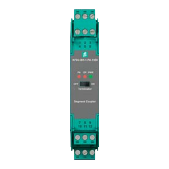
- Page 1 PROCESS AUTOMATION MANUAL FieldConnex Basic ® Segment Coupler KFD2-BR-1.PA.1500 ®...
- Page 2 FieldConnex® Basic Segment Coupler With regard to the supply of products, the current issue of the following document is ap- plicable: The General Terms of Delivery for Products and Services of the Electrical Indus- try, published by the Central Association of the Electrical Industry (Zentralverband Elektrotechnik und Elektroindustrie (ZVEI) e.V.) in its most recent version as well as the supplementary clause: "Expanded reservation of proprietorship"...
-
Page 3: Table Of Contents
FieldConnex® Basic Segment Coupler Introduction................. 5 Contents....................5 Target Group, Personnel..............5 Symbols Used ..................5 Product Specifications............... 7 Overview and Application ..............7 Component Overview and Dimensions ..........8 Technical Data ..................8 Installation................. 11 Mounting Options ................11 3.1.1 DIN Mounting Rail................ - Page 4 FieldConnex® Basic Segment Coupler Appendix ................... 26 Ordering Information................26 Electromagnetic Compatibility Verification ........26 Referenced Documents ..............27...
-
Page 5: Introduction
FieldConnex® Basic Segment Coupler Introduction Introduction Contents This document contains information that you need in order to use your product throughout the applicable stages of the product life cycle. These can include the following: Product identification ■ Delivery, transport, and storage ■... - Page 6 FieldConnex® Basic Segment Coupler Introduction Warning Messages You will find warning messages, whenever dangers may arise from your actions. It is mandatory that you observe these warning messages for your personal safety and in order to avoid property damage. Depending on the risk level, the warning messages are displayed in descending order as follows: Danger! This symbol indicates an imminent danger.
-
Page 7: Product Specifications
Product Specifications Overview and Application The Pepperl+Fuchs basic Segment Coupler is intended to transparently couple a PROFIBUS PA segment to PROFIBUS DP. Due to the transparent coupling, PROFIBUS PA devices are represented as devices that are directly connected to a PROFIBUS DP segment. -
Page 8: Component Overview And Dimensions
FieldConnex® Basic Segment Coupler Product Specifications Conversion of the PROFIBUS DP to the physical layer on the PROFIBUS PA ■ Adaptation of DP and PA transfer rates ■ Electrical isolation between PROFIBUS DP and PA ■ LEDs for basic function diagnostics ■... - Page 9 FieldConnex® Basic Segment Coupler Product Specifications Technical Data PROFIBUS PA Connection 3+, 6+, 2-, 5-, 1 shield, 4 shield Rated voltage 24 ... 26 V Rated current max. 400 mA Terminating impedance 100 , integrated PROFIBUS DP PROFIBUS with RS-485 transmission technology Connection terminals 7 RxD/TxD-P, 8 RxD/TxD-N, 9 shield, 10 FE Baud rate...
- Page 10 FieldConnex® Basic Segment Coupler Product Specifications Technical Data Housing material Polycarbonate Degree of protection IP20 Mass 180 g Mounting DIN rail mounting Data for application in connection with Ex-areas Statement of conformity TÜV 16 ATEX 7831 X Group, category, type of II 3G Ex ec IIC T4 Gc protection, temperature class Directive conformity...
-
Page 11: Installation
FieldConnex® Basic Segment Coupler Installation Installation In the following section you find information on how to install the device in your fieldbus topology. Danger! Explosion hazard from exposure to potentially explosive gas atmosphere If the device is installed in Zone 2 without mounting it in a sufficiently suitable enclosure, gas, dust, water or other external interferences can cause the live device to spark. -
Page 12: Din Mounting Rail
FieldConnex® Basic Segment Coupler Installation 3.1.1 DIN Mounting Rail The devices are mounted on a 35 mm DIN mounting rail according to EN 60715. Figure 3.1 Example: DIN mounting rail UPR-MR (35 mm x 15 mm) 3.1.2 Power Rail To reduce wiring and installation costs, Power Rail is the optimum solution. The Power Rail is a DIN mounting rail with plastic insert, that delivers power to the devices (24 V DC) and transfers bus signals and a collective error message. - Page 13 FieldConnex® Basic Segment Coupler Installation Power Rail UPR-03 The Power Rail UPR–03 comprises 3 leads. 2 conductors for power ■ 1 conductor for collective error messaging ■ Figure 3.2 Example: Power Rail UPR-03 Cover UPR-COVER Insert UPR-INS-03 DIN mounting rail UPR-MR (35 mm x 15 mm) End cap UPR-E...
-
Page 14: Mounting And Dismounting
FieldConnex® Basic Segment Coupler Installation Mounting and Dismounting The following chapter describes how to mount or dismount the device. 3.2.1 Mounting Mounting the Device Snap the device onto the DIN mounting rail in a vertical downward movement. See figure below. CORRECT: Device snapped on vertically. - Page 15 FieldConnex® Basic Segment Coupler Installation Danger! Explosion hazard from connection damage Manipulating connections outside of the specified ambient temperature range can lead to material damage, resulting in an unwanted failure of the connection. This could result in an increased explosion hazard in potentially explosive atmospheres. Only manipulate connections in the specified ambient temperature range.
-
Page 16: Power Supply Without Power Rail
FieldConnex® Basic Segment Coupler Installation Screw Terminals: Cable and Connection Information Permissible wire core section: ■ Screw terminals with flexible or rigid wires: 0.2 ... 2.5 mm² Insulation stripping length: 7 mm ■ If you use stranded connectors: Crimp on wire end ferrules ■... - Page 17 FieldConnex® Basic Segment Coupler Installation Alternatively, supply of the Power Rail can be provided using the power supply KFA6-STR- 1.24.*. Non-Redundant Supply with Power Feed Modules The power feed module mounts on the Power Rail for easy and reliable distribution of power to all connected isolators.
- Page 18 FieldConnex® Basic Segment Coupler Installation Redundant Supply with Power Feed Modules Two power supplies or a redundant power supply with two power feed modules offer a high degree of availability. If a power supply or the fuse in a power feed module fails, the redundant supply continues to energize the isolators through their Power Rail connection.
-
Page 19: Shielding And Grounding
FieldConnex® Basic Segment Coupler Installation Direct Supply with Power Supplies A complete power solution for a K-System installation is possible by using the following power supply: KFA6-STR-1.24.4 from 115/230 V AC to 24 V DC/4 A ■ The power supplies snap on the Power Rail to easily and efficiently distribute power to the isolated barriers. -
Page 20: Bus Termination
FieldConnex® Basic Segment Coupler Installation KFD2-BR-1.PA.1500 DP PWR Terminator Segment Coupler Figure 3.7 Stylized composition of the shield lines inside the KFD2-BR-1.PA.1500 Bus Termination The Segment Coupler includes a fixed terminator on the PROFIBUS PA side and a switchable terminator on PROFIBUS DP side. Ensure that the physical ends of the segments are terminated on both segments in order to avoid reflection. -
Page 21: Commissioning
FieldConnex® Basic Segment Coupler Commissioning Commissioning In the following section you find information on how to commission the device in your fieldbus topology. Note! Read the instruction manual first! Before you install and commission this product: Read the instruction manual for this product carefully. - Page 22 If you need a conversion tool in order to convert PA GSD files into DP GSD files, you can use the Pepperl+Fuchs GSD converter free of charge. Download Free Software Tool If needed, download the Pepperl+Fuchs GSD converter from the product information page of the device you obtained at www.pepperl-fuchs.com.
-
Page 23: Information On Watchdog Time (Twd)
Note! The advisory board of the PROFIBUS user organization has agreed not to rescind the certification of GSD files that are modified using Pepperl+Fuchs GSD converter software. In order to convert GSD files, proceed as follows: 1. Start the program PFGSDCX.EXE The following dialog window appears: 2. - Page 24 = cycle time of the PROFIBUS PA channel cycle_PA_channel = cycle time of PROFIBUS DP cycle_DP Pepperl+Fuchs recommends a value 3 x the PROFIBUS PA cycle time. The PA cycle time T depends on the following aspects: cycle_PA_channel Number of devices attached to the bus on 1 channel n ■...
-
Page 25: Operation
4. Configure your PROFIBUS PA devices in your system. Check that the GSD files of the PROFIBUS PA devices in use contain the baud rate you intend to configure in your PROFIBUS DP master. If this is not the case, run the Pepperl+Fuchs GSD converter pro- gram. - Page 26 FieldConnex® Basic Segment Coupler Appendix Appendix Ordering Information Accessories Type Code Description UPR–03 Universal Power Rail ® KFD2–EB2 Power feed module KFD2–EB2.R4A.B Redundant power feed module Electromagnetic Compatibility Verification Verification in Accordance with EC Council Legislation Directive 2004/108/EC and 2014/30/EU Compatibility in Accordance with EN 61326-1 and NAMUR NE 21 Recommendation The electromagnetic compatibility (EMC) requirements, applicable for electrical equipment for...
- Page 27 Reduction factor conducted emission Class A Reduction factor radiated emission Class A Referenced Documents Manual: "Using Pepperl+Fuchs Fieldbus Equipment in Zone 2 Hazardous Area ■ Environment" PROFIBUS & PROFINET International (PI): PROFIBUS PA Installation Guideline. ■ Manual: System Description K-System.
- Page 28 PROCESS AUTOMATION – PROTECTING YOUR PROCESS Worldwide Headquarters Pepperl+Fuchs GmbH 68307 Mannheim · Germany Tel. +49 621 776-0 E-mail: info@de.pepperl-fuchs.com For the Pepperl+Fuchs representative closest to you check www.pepperl-fuchs.com/contact www.pepperl-fuchs.com Subject to modifications / DOCT-4892 Copyright PEPPERL+FUCHS • Printed in Germany 04/2016...
Need help?
Do you have a question about the FieldConnex KFD2-BR-1.PA.1500 and is the answer not in the manual?
Questions and answers