Table of Contents
Advertisement
Advertisement
Table of Contents

Related Manuals for FLIR MR277


Summary of Contents for FLIR MR277
- Page 1 USER MANUAL Moisture Meter, MSX® IR Camera, Hygrometer Model MR277...
- Page 3 USER MANUAL Moisture Meter, MSX® IR Camera, Hygrometer #NAS100005; r. AG/62027/62027; en-US...
-
Page 5: Table Of Contents
Measurement Menu ..........12 Moisture Modes Menu ..........14 Color Menu ............. 16 Settings Menu............17 Powering the MR277 ............23 Moisture Measurement Operation ........24 Moisture Measurements Basics ........24 Moisture Display Options..........25 IGM™ Moisture and IGM™ Custom Modes....27 Moisture Measurement Modes ........ - Page 6 Progressive Environmental Stability Indicator for RH % ................42 Capturing and Working with Screen Captures....... 43 10.1 Capturing Images ............. 43 10.2 Viewing Images on the MR277 ........43 10.3 Deleting images ............43 10.4 Transferring Images via PC Interface......43 10.5 Transmitting Images and Data via Bluetooth®....
- Page 7 Table of contents Limited 10–Year Warranty ........... 60 Customer Support............. 61 17.1 Corporate Headquarters ..........61 #NAS100005; r. AG/62027/62027; en-US...
-
Page 9: Advisories
Advisories 1.1 Copyright ©, FLIR Systems, Inc. All rights reserved worldwide. No parts of the soft- ware including source code may be reproduced, transmitted, transcribed or translated into any language or computer language in any form or by any means, electronic, magnetic, optical, manual or otherwise, without the prior written permission of FLIR Systems. -
Page 10: Introduction
Introduction Thank you for selecting the FLIR MR277. The MR277 integrates high quality thermal imaging and digital camera technology with best-in-class moisture detection and measurement. The MR277 includes an integrated noninvasive pinless moisture sensor, an external pin moisture probe (MR02), and a re- placeable temperature and relative humidity ambient sensor (MR13). - Page 11 Introduction • Easily capture, view, download (to PC), send to mobile devices, and delete camera images • Selectable material groups allow you to fine tune pin-based measurements • Programmable high moisture alarm and high/low radiometry alarm with audible and color-coded display alerts •...
-
Page 12: Safety
Safety 3.1 Safety Warnings and Cautions WARNING Before operating this device, please read, understand, and follow all operational instruc- tions and safety warnings. CAUTION Use of controls or adjustments or performance of procedures other than those specified herein may result in hazardous radiation exposure. CAUTION Use extreme caution when the Laser pointer is on. -
Page 13: Descriptions
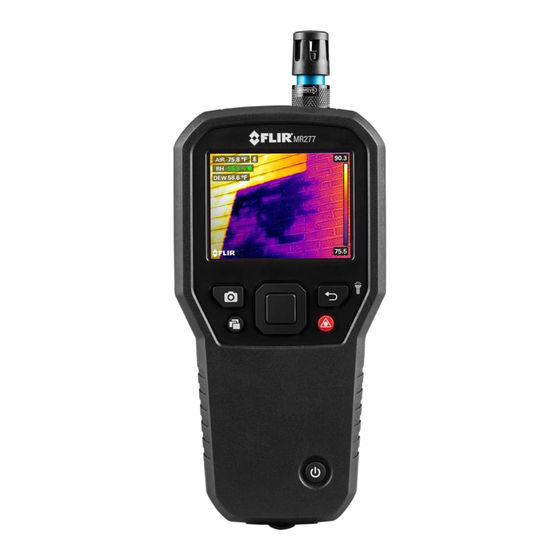
Descriptions 4.1 Product Description Figure 4.1 Front, Back, and Bottom Product Description 1. Temperature and Relative Humidity Sensor (MR13) 2. Color Graphical Display 3. Image Capture button 4. Image Gallery button 5. Select button (center). Press to open Menu 6. Power button 7. -
Page 14: Control Button Descriptions
Press to switch the Laser pointer ON. Press to capture screen image. Press to open image gallery. 4.3 Display Description Figure 4.2 MR277 Select Display Descriptions 1. Moisture reading 2. Temperature of targeted center spot (cross hairs) 3. Air temperature (from probe measurement) 4. - Page 15 Descriptions 8. IR Thermal image 9. Cross-hairs (Center Spot) 10. Low end of IR image temperature range 11. High end of IR image temperature range 12. Temperature scale 13. Laser pointer active icon 14. Bluetooth® active icon NOTE Not all icons are represented in Figure 4–2. Other available icons are explained in their re- spective sections of this user manual.
-
Page 16: User Interface Menus
When the Select button is pressed, six menu icons appear along the bot- tom of the MR277 display. Use the left/right navigation buttons to move to a menu icon, and use the Select button to open a selected menu. Once a menu is opened, the navigation and Select buttons are used to select modes of op- erations and settings. -
Page 17: Temperature Scale Menu
Use the navigation buttons to move to the desired setting and then press Select to confirm. In Automatic mode, the MR277 automatically selects the temperature range for each thermal image, based on the highest and lowest temperatures de- tected. In Lock mode, you can ‘lock in’ a particular thermal image’s tempera- ture range and use this locked range for subsequent thermal image comparisons. -
Page 18: Image Mode Menu
User Interface Menus 5.4 Image Mode Menu Figure 5.4 Six Main Menu icons The Image Mode Menu offers six sub-menus as described below. • Alignment Distance control: This control allows you to adjust the super- imposition of the visible image over the thermal image. This is the MSX® feature. - Page 19 User Interface Menus Figure 5.6 Thermal MSX® selection • Thermal mode: Select this mode to see the thermal image only. Figure 5.7 Thermal IR Image mode • Digital Camera mode: Select this mode to see only the visible camera image. Figure 5.8 Digital Camera mode selection •...
-
Page 20: Measurement Menu
User Interface Menus ratio, and Vapor Pressure values, derived from the RH and Temperature measurements. Figure 5.9 Psychrometrics mode selection and display example • Moisture mode: Select this mode to see only the moisture reading in large digit format. Figure 5.10 Moisture mode selection and example screen 5.5 Measurement Menu The Measurement Menu offers four sub-menus as described below. - Page 21 User Interface Menus • No Measurements: Select this mode if you do not wish to see any meas- urement values or icons on the display. Only the camera image will be seen in this mode. Figure 5.12 Selecting the ‘No Measurement’ mode from the main menu •...
-
Page 22: Moisture Modes Menu
Figure 5.14 Selecting the IGM™ Moisture mode from the main menu • IGM™ Custom mode: Select this mode to view all of the measurement types on the MR277 that you enable in the Settings menu (see Section 5.8). Figure 5.15 Selecting the IGM™ Custom mode from the main menu 5.6 Moisture Modes Menu... - Page 23 7.6 External Pin Probe Measurements for more information. Figure 5.18 Selecting pin-based measurement mode • Pinless mode: Select this mode when using the pinless sensor (rear of MR277). See Section 7.5 Pinless Moisture Measurements for more information. Figure 5.19 Selecting the pinless measurement mode...
-
Page 24: Color Menu
Figure 5.20 Selecting the MR12 (optional moisture probe) mode • Set Reference mode: This utility is only available when using the built-in pinless sensor (rear of MR277) or the remote MR12 Ball Moisture probe. After selecting the pinless mode (or the MR12 mode) and while taking a moisture measurement, select the ‘Set Reference’... -
Page 25: Settings Menu
User Interface Menus Figure 5.22 Color palette selections 5.8 Settings Menu The Settings menu offers the following options: #NAS100005; r. AG/62027/62027; en-US... - Page 26 User Interface Menus Figure 5.23 Selecting the ‘Settings’ mode from the main menu Figure 5.24 Settings menu • IGM™ Custom mode: Select the readings that you wish to display when the IGM™ Custom Mode is enabled in the Measurement Menu, Section 5.5.
- Page 27 • Date and time setting: Set the year, month, day, hours, and minutes. Figure 5.28 Setting the Date and Time • Connections: Set Bluetooth® communications ON or OFF. See Section 11 Bluetooth® Communication and FLIR Tools™ for more information. #NAS100005; r. AG/62027/62027; en-US...
- Page 28 • Radiometry & Moisture Alarms: Set the Radiometry (temperature) Alarm to ABOVE, BELOW, or OFF. When a Radiometry alarm is set to ABOVE or BELOW, the MR277 will alert you when the temperature exceeds the high limit (temperature display turns red) or falls below the low limit (temperature display turns blue).
- Page 29 User Interface Menus Figure 5.31 Enabling/Disabling the Laser pointer and the Worklight • Auto Power OFF (APO): Set APO to a time value of 5, 10, 20, or 30 mi- nutes. Set to OFF to disable APO. Figure 5.32 Setting the Auto Power Off (APO) utility •...
- Page 30 (erase) the internal storage bank. To recover from a MR277 crash (display freezes), press and hold the UP and DOWN arrows for >10 seconds, until the MR277 reboots. No data will be lost by running this procedure.
-
Page 31: Powering The Mr277
ON, charge the battery by connecting the meter to an AC charger using the supplied USB cable. When the MR277 is not charging, the battery status indicator is only visible from the Main Menu (press Select to access the Main Menu). -
Page 32: Moisture Measurement Operation
MR12 Ball Moisture probe, to the RJ jack at the bot- tom of the meter. Other external probes are available optionally; please visit https://www.flir.com for details. The MR277 has a dedicated MR12 utility where you connect the probe and select the MR12 icon in the ‘Moisture Mode’... -
Page 33: Moisture Display Options
Moisture Measurement Operation Moisture measurements are covered in detail in the following sections. Be sure to select Pin Mode or Pinless Mode in the ‘Moisture’ menu to match the measurement type. 7.2 Moisture Display Options View moisture readings in two basic ways. 1. Moisture readings as large digits in the Moisture-only mode or 2. - Page 34 Moisture Measurement Operation Figure 7.3 Thermal mode with Moisture reading in the upper left corner • Digital Camera: This is the digital camera image only. The moisture read- ing can be seen on the upper left. Figure 7.4 Digital Camera mode with Moisture reading in the upper left corner •...
-
Page 35: Igm™ Moisture And Igm™ Custom Modes
Moisture Measurement Operation Figure 7.5 Psychrometrics display mode • Moisture mode. This is a dedicated display for moisture only. Large digits and a bar graph are used in this mode for easy viewing. Additional features in this mode include color coded alarm alert (see Section 7.9 High Mois- ture Alarm) and relative readings (see Section 7.8 Set Reference). -
Page 36: Moisture Measurement Modes
Moisture Measurement Operation Figure 7.7 IGM™ mode with Moisture reading shown on upper left In the IGM™ Custom mode , the same benefits apply to the discussion above for IGM™ Moisture mode with the added benefits of displaying Air Temperature, Relative Humidity, Vapor Pressure, Mixing Ratio, and Dew Point Temperature on the camera image. - Page 37 Moisture Measurement Operation selection (Moisture Mode/Material ). Use the Navigation arrows to scroll through the Material list and press Select to choose the Group number. See the Material Group tables in Section 15 Appendices, these tables will help you decide which Material Group to select. Figure 7.9 Selecting a Material Group in the ‘Moisture’...
- Page 38 MR12 mode must be selected when the optional MR12 Ball Moisture probe is used. Connect the MR12 to the accessory RJ jack on the bottom of the MR277 (under the protective flap) and then select the MR12 from the Moisture Mode menu as shown in Figure 7–12.
-
Page 39: Pinless Moisture Measurements
7.4, for more information. • Keep hands, surfaces, and objects away from the internal moisture sensor on the back of the MR277 when taking measurements. • For best results, lift the meter off the surface under test between measure- ment points;... -
Page 40: Mr12 Ball Moisture Probe (Optional)
NOTE Pin Probe Moisture Measurement Considerations The MR277 will display accurate external pin probe readings in the 7% to 30% range, de- pending on the tested material. Moisture Content readings below 6% will display as 0% for all materials and the maximum specified range is dependent on the fiber saturation point for specific species. -
Page 41: Set Reference Mode
Moisture Measurement Operation 7.8 Set Reference Mode 1. Select the ‘Set Reference’ mode from the menu (Moisture mode/Set Reference ); see Figure 7–13 above. This mode is only available for pinless measurements, including the optional MR12 Ball Moisture probe. 2. When the ‘Set Reference’ mode is selected, the displays are affected in the following ways: •... -
Page 42: High Moisture Alarm
Moisture Measurement Operation 7.9 High Moisture Alarm 1. To access the Alarm mode use the menus (Settings/Radiometry & Mois- ture Alarm mode). See Section 8.4 for High/Low Radiometry (Tempera- ture) Alarm mode. Figure 7.14 Setting the Moisture Alarm 2. Select the ‘Set Moisture Alarm’ mode. 3. - Page 43 Moisture Measurement Operation 6. If the beeper is enabled in step 3 above, the beeper will sound when the moisture exceeds the threshold. To silence the beeper when the meter is alarming, press Select . The meter will open the ‘Settings’ menu where you can opt to turn the beeper OFF or otherwise program the alarm parameters.
-
Page 44: Thermal And Visible Camera Operation
Section 5.4 Image Mode Menu. The Thermal Camera lens is located on the back of the meter. Face the lens toward the area of interest and view the image on the MR277 display. Select the thermal image color palette from the menu ( Color). - Page 45 Thermal and Visible Camera Operation Figure 8.1 Color Palette options On the right side of the thermal images, a vertical bar graph provides a tem- perature scale for convenience. The top of the scale shows the hotter pixels in the frame, and the lower part of the scale shows the colder pixels. Digital readouts appear on the top and bottom of the bar graph to show the high and low range limits for the camera image.
-
Page 46: Automatic/Lock Temperature Scaling
Thermal and Visible Camera Operation Cross-hairs are visible when ‘Center Spot’ is selected from the ‘Measurement’ menu (Measurement mode). Cross-hairs are also visible in the ‘Custom IGM™ mode’ when ‘Radiometry’ is selected in the ‘Custom IGM™’ menu in the ‘Settings’ menu (Settings/Custom IGM™). 8.2 Automatic/Lock Temperature Scaling Note: For best results, allow a warm-up period of 3-5 minutes before using this feature. -
Page 47: Digital (Visible) Camera
Thermal and Visible Camera Operation 8.3 Digital (Visible) Camera Select the full screen Digital Camera from the menu system: Select button/Im- age Mode/Digital Camera Figure 8.3 Selecting the Digital Camera image The Digital Camera lens is located on the back of the meter. Face the lens to- ward the area of interest and view the image on the display. - Page 48 Thermal and Visible Camera Operation 3. Use the navigation arrows and Select button to set the Alarm (ABOVE, BELOW, or OFF) and to set the temperature limit. There is no beeper available for the Radiometry alarms so the ‘No Sound’ setting cannot be changed.
-
Page 49: Ambient Temperature And Humidity Measurements
9.1 Temperature & RH Measurements and Dew Point, Vapor Pressure, and Mixing Ratio Calculations The removable MR13 connects to the top of the MR277 and senses ambient Temperature and Relative Humidity. Calculations based on these Tempera- ture and Relative Humidity measurements are also provided. These calcula- tions are Dew Point Temperature, Vapor Pressure (in units of kilo-Pascals), and Mixing ratio (in Grains Per Pound). -
Page 50: Progressive Environmental Stability Indicator For Rh
9.2 Progressive Environmental Stability Indicator for RH% The Progressive Environmental Stability Indicator is useful for determining when relative humidity readings on the MR277 have stabilized (for example, when taking ambient readings in an air duct). The circle next to the RH% display line fills and turns green when the relative humidity reading stabilizes. -
Page 51: Capturing And Working With Screen Captures
Connect the MR277 to a Windows™ or Apple™ computer’s USB port using the supplied USB cable. The USB jack is located on the bottom of the MR277, under the protective flap. Once connected, the MR277 can be used as you would any external storage drive. -
Page 52: Transmitting Images And Data Via Bluetooth
Capturing and Working with Screen Captures 10.5 Transmitting Images and Data via Bluetooth® The MR277 images and reading data can be transmitted to a mobile device running the FLIR Tools™ App. In addition, MR277 readings can be viewed on certain FLIR cameras. -
Page 53: Bluetooth® Communication And Flir Tools
Select INSTRUMENTS from the drop-down menu in the App and search for the MR277 (the MR277 must be ON). Tap in the App to connect to the MR277. When connected to a device running the App, the MR277 (using the METER- LiNK®... - Page 54 Bluetooth® Communication and FLIR Tools™ 4. Consult the dealer or an experienced radio/TV technician for help. WARNING Changes or modifications not expressly approved by the party responsible for compliance could void the user’s authority to operate the equipment. #NAS100005; r. AG/62027/62027; en-US...
-
Page 55: Field Firmware Updates
3. Select the MR277 from the second drop-down menu. 4. Select and download the firmware update file to the PC. 5. With the MR277 ON connect it to the PC via the supplied USB cable. 6. Copy the firmware update file to the MR277 root directory. -
Page 56: Maintenance
The rechargeable lithium battery is not user-serviceable. Please contact FLIR support for service instructions: https://support.flir.com. If the MR277 is not going to be used for > 3 months, it should be charged to at least 70% then stored at room temperature and recharged every 6 months. -
Page 57: Specifications
USB cable Language options Multi-language support for programming menus 14.2 Imaging Specifications Thermal imaging camera FLIR Lepton®, microbolometer FPA (focal plane array) Image calibration Automatic (with lock-scale option: see Tempera- ture Scale option from the Main Menu) #NAS100005; r. AG/62027/62027; en-US... -
Page 58: Moisture Meter Specifications
Specifications Thermal image resolution 160(W) x 120(H) pixels 8~14µm Spectral response Field of view 71° horizontal x 51° vertical Thermal Sensitivity < 150mK Detection Limit Wet area detection @ 32’ (10m): 19.7in (49cm Thermal frame update rate 9 Hz Thermal image palettes Selectable: Iron, Rainbow, White hot, Black hot, and Arctic Minimum focus distance... -
Page 59: Safety Specifications
Specifications 14.5 Safety Specifications General Safety CE/EN/UL/CSA/PSE 61010 Environmental Safety REACH Regulation EC 1907/2006 RoHS2 Directive 2011/65/EC WEEE Directive 2012/19/EC JIS C 6802:2011 laser directive IEC 60825-1 class II laser directive FDA Laser directive Encapsulation IP54 (IEC 60529) with bottom flap fully sealed Drop-proof Designed to 6.6 ft. -
Page 60: Appendices
Appendices 15.1 Material Groups 15.1.1 Common names of timbers (BS888/589:1973) with MR277 Group Numbers NOTE Use Group 9 for building materials: plywood, drywall, and oriented strand board (OSB). Use Group 10 for brick, cement screed, and concrete. Use Group 11 for cement mortar, anhydrite screed, lime mortar, and plaster. - Page 61 Appendices Beech, European Kuroka Pine, Ponderosa Berlina Larch, Pine, Radiata European Pine, Red Binvang Larch, Japanese Birch, European Larch, Western Pine, Scots Birch, Yellow Lime Pine, Sugar Bisselon Loliondo Pine, Yellow Poplar, Black Bitterwood Mahogany, African Blackbutt Mahogany, Pterygota, West Indian African Bosquiea Makore...
- Page 62 Appendices Muninga Cypress, Japa- Silky Oak, nese (18-28% African Cypress, Japa- Musine Silky Oak, nese (8-18%mc) Australian Dahoma Musizi Spruce, Japa- nese (18-28% Danta Myrtle, Spruce, Japa- Tasmanian nese (8-18% Douglas Fir Naingon Spruce, Nor- (European) Elm, English Oak, American Spruce, Sitka Elm, Japanese Oak, American...
-
Page 63: Botanical Names Of Timbers
Appendices Panga Panga Walnut, Gum, Saligna Queensland Gum, Southern Persimmon Wandoo Gum, Spotted Pillarwood Wawa Whitewood 15.1.2 Botanical names of timbers Material Group Material Group Material Group Abies alba Eucalyptus Picea jezoensis acmenicides (8-18%mc) Picea sitchensis Abies grandis Eucalyptus crebra Abies procera Eucalyptus Pinus caribaea... - Page 64 Appendices Fraxinus Pinus thunbergii Amblygonocar- pus andogensis Americana Amblygonocar- Fraxinus Pipadeniastrum pus obtusungulis excelsior africanum Fraxinus Piptadenia Araucaria angustifolia japonicus africana Araucaria bidwilli Fraxinus Podocarpus mardshurica dacrydiodes Podocarpus Araucaria Gonystylus cunninghamii spicatus macrophyllum Berlinia Podocarpus Gossweiloden- grandiflora totara dron balsamiferum Berlinia spp Populus spp Gossypiosper-...
- Page 65 Appendices Ricinodendron Cassipourea Larix kaempferi elliotii heudelotti Cassipourea Larix leptolepis Sarcocephalus melanosana diderrichii Larix Castanea sutiva Scottellia occidentalis coriacea Liquidamper Cedrela odorata Sequoia styraciflua sempervirens Lovoa klaineana Ceratopetalum Shorea spp apetala Chamaecyparis Lovoa Sterculia spp (18-28%mc) trichiloides rhinopetala Maesopsis Chamaecyparis Swietenia eminii spp (8-18%mc)
-
Page 66: Wme Table (% Wood Moisture Equivalent)
Appendices Tilia vulgaris Dracontomelium Olea mangiferum hochstetteri Dryobanalops Triploehiton Olea welwitschii scleroxylon Dyera costulata Palaquium spp Tsuga heterophylia Endiandra Paulownia Ulmus palmerstoni tomentosa americana Entandrophrag- Pericopsis elata Ulmus procera ma angolense Picaenia excelsa Ulmus thomasii Entandrophrag- ma cylindricum Entandrophrag- Picea abies Xylia ma utile dolabriformis... - Page 67 Appendices 20.8 23.5 18.5 17.6 16.8 19.1 22.3 18.3 21.5 24.5 19.3 18.3 17.4 19.7 23.2 19.1 22.9 26.4 20.2 19.8 18.6 21.2 25.3 19.9 23.5 27.4 20.8 20.4 25.8 20.5 24.2 27.8 21.2 19.4 22.7 26.3 ≈23 25.3 22.4 22.3 20.1 23.9...
-
Page 68: Limited 10–Year Warranty
Limited 10–Year Warranty This product is protected by FLIR’s Limited 10-Year Warranty. Visit https://support.flir.com/prodreg to read the Limited 10-Year Warranty document. #NAS100005; r. AG/62027/62027; en-US... -
Page 69: Customer Support
Customer Support Repair, Calibration, and Technical Support: https://support.flir.com. 17.1 Corporate Headquarters FLIR Systems, Inc. 27700 SW Parkway Avenue Wilsonville, OR 97070 USA #NAS100005; r. AG/62027/62027; en-US... - Page 70 #NAS100005; r. AG/62027/62027; en-US...
- Page 72 Customer support http://support.flir.com Copyright © 2019, FLIR Systems, Inc. All rights reserved worldwide. Disclaimer Specifications subject to change without further notice. Models and accessories subject to regional market considerations. License procedures may apply. Products described herein may be subject to US Export Regulations.
Need help?
Do you have a question about the MR277 and is the answer not in the manual?
Questions and answers