
Related Manuals for Olivetti C3520MFP


Summary of Contents for Olivetti C3520MFP
- Page 1 MF1600 d-Color MF2000 User’s Guide The Olivetti d-Color MF1600 and d-Color MF2000 models use OKI software equivalent to the models C3520MFP and C3530MFP.
- Page 2 PUBLICATION ISSUED BY: Olivetti S.p.A. Gruppo Telecom Italia Via Jervis, 77 - 10015 Ivrea (ITALY) www.olivetti.com Copyright © 2007, Olivetti All rights reserved mark affixed to the product certifies that the product satisfies the basic quality May 2007 requirements. The manufacturer reserves the right to carry out modifications to the product described in this manual at any time and without any notice.
-
Page 3: Ontents Preface
Every effort has been made to ensure that the information in this document is complete, accurate, and up-to-date. Olivetti assumes no responsibility for the results of errors beyond its control. Olivetti also cannot guarantee that changes in software and equipment made by other manufacturers and referred to in this guide will not affect the applicability of the information in it. -
Page 4: Emergency First Aid
MERGENCY IRST Take care with toner powder: If swallowed, induce vomiting and seek medical attention. Never attempt to induce vomiting if person is unconscious. If inhaled, move the person to an open area for fresh air. Seek medical attention. If it gets into the eyes, flush with large amounts of water for at least 15 minutes keeping eyelids open. -
Page 5: Table Of Contents
ONTENTS Preface ........2 Emergency First Aid ......3 Importer to the EU . - Page 6 The Scanner/Copier section ....40 Minimum Configuration Requirements..40 Internet Communication Features ... . 40 Pre-Installation Information.
- Page 7 Fax problems (d-Color MF2000) ....113 Installing additional memory ....116 Memory upgrade .
-
Page 8: Notes, Cautions And Warnings
For the protection of your product, and in order to ensure that you benefit from its full functionality, this model has been designed to operate only with genuine Olivetti toner cartridges. Any other toner cartridge may not operate at all, even if it is described as "compatible", and if it does work,... -
Page 9: Introduction
NTRODUCTION Congratulations on choosing this Multi Function Product (MFP). It has been designed with advanced features, to give you clear, vibrant colour prints and crisp black and white pages at high speed, on a range of office print media. With this MFP, you can instantly scan paper-based documents and deliver the electronic image to various destinations including email addresses, printers, ftp servers, facsimile machines, USB memory stick, or someone else's computer on the network. - Page 10 > 300 x 300 (standard) and 600 x 600dpi (high) copy resolution. > Banner Printing (d-Color MF2000). > Single Pass Colour Digital LED technology for high speed processing of your printed pages. > High speed USB 2.0 interface. > 10Base-T and 100Base-TX network connection lets you share this resource among users on your office network.
- Page 11 > Multiple Pages Sending - With the Auto Document Feeder, the MFP allows a stack of up to 50 page document(s) to be continuously scanned. > Simplified Operator panel > Address Book/Profiles Managing - This provides a convenient way to manage all the e-mail addresses and profiles (filing destinations).
-
Page 12: Mfp Overview
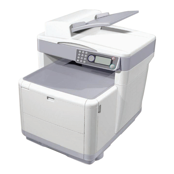
OVERVIEW RONT VIEW 1. Scanner bed. 6. Output stacker, face down. Standard printed copy delivery point. Holds up to 150 sheets of 80g/m². 2. Automatic Document 7. Standard paper tray with level Feeder (ADF) Unit.ADF indicator. Holds up to 250 sheets of Paper Tray. -
Page 13: Rear View
EAR VIEW This view shows the connection panel and the rear output stacker. TEST LINE 1. USB connection. 5. IEC (CE22) AC power connection. 2. Local Area Network 6. AC Power ON/OFF switch. connection. 3. Local Telephone handset Automatic Document Feeder (ADF). connection. -
Page 14: The Operator Panel
PERATOR ANEL abcd@d Done a b c e f g h i j k l m n o p q r s t u v w x y z 1. Key Pad Used to enter numbers, upper-case/lower-case letters and symbols in the Entry Line. 2. - Page 15 abcd@d Done a b c e f g h i j k l m n o p q r s t u v w x y z 6. RIGHT Key When in switching Mode: Used to confirm the Mode selected. Used to start Push Scan (If Push Scan is selected, the Executing Push Scan screen appears).
-
Page 16: Languages Supported
ANGUAGES UPPORTED English German French Italian Spanish Swedish Norwegian Danish Dutch Portuguese Greek Brazilian Portuguese Russian Polish Turkish Czech Hungarian Finnish NOTES: 1. This list is not exhaustive or conclusive. 2. See the information enclosed with the product (the Panel Language Setup utility) on the procedure for changing the language setting. -
Page 17: Getting Started
ETTING TARTED NSTALLING DRIVERS AND TILITIES NOTE: You must be logged on as an administrator or a member of the Administrators group in order to complete this procedure. If your computer is connected to a network, network policy settings may also prevent you from completing this procedure. - Page 18 If CD autoboots, cancel the dialogue. The ‘New Hardware Found' dialogue will appear on the screen. If you do not see the ‘New Hardware Found' dialogue, please check that power and USB cables are connected properly, and the printer is switched on. Install Twain driver first Getting Started >...
- Page 19 Next install the Printer driver Getting Started > 18...
-
Page 20: Fax Printer Driver (D-Color Mf2000 Only)
(d-Color MF2000 RINTER DRIVER ONLY The Fax Printer Driver allows you to send faxes directly from your computer without printing the document first. Windows XP has built-in fax support - you can use your computer's modem to send faxes directly from your computer. With fax driver you are sending the fax data from your computer to the MFP, and then the MFP automatically sends the document. - Page 21 Select Settings. The following screen will appear. Select the function you want to set in section (1). Set the parameters for this function in section (2). When you have completed settings, press OK (3). The Utility will return to the Hotkey console (para. 2 above).
-
Page 22: Mfp Setup Tool
MFP S ETUP TOOL Installation of the MFP setup utility is optional and can be found on the Driver/Utilities CD under the Utilities folder. The setup program does not automatically place an icon on your desktop. If you wish, you can drag and drop this icon on to your desktop for ease of future use. - Page 23 MFP Settings: Allows you to change most of the same settings as you'd see on the MFP's operator panel, on a locally connected PC. The settings include an Admin. menu. This is password protected and hidden by default. To enable the Admin menu, select: Setting>MFP Setting>Display >...
- Page 24 Phone Book Manager (d-Color MF2000 only): For managing people and fax numbers (for "scan to fax" feature of MFP). Add names, fax numbers, assign them to speed dial numbers. > Arrange people into groups. > Import and export settings to CSV files. >...
-
Page 25: Scanner/Copier Section
PIN Manager: The MFP can have access control switched on the front panel. If this is the case, a PIN (Personal Identification Number) is required to use the MFP. The PIN Manager creates PIN numbers and assigns them rights such as whether they can copy, print, scan to email, scan to network PC or fax. -
Page 26: Printer Section
RINTER SECTION APER RECOMMENDATIONS Your MFP will handle a variety of print media, including a range of paper weights and sizes. This section provides general advice on choice of media, and explains how to use each type. The best performance will be obtained when using standard 75~90g/m²... -
Page 27: Cassette Tray
ASSETTE TRAY The Cassette Tray can handle paper weights of 64g/m² to 176g/ m². The Cassette Tray is ideal for printing A4 documents of more than 1 page in length. SIZE DIMENSIONS WEIGHT (G/M²) 105 x 148mm 148 x 210mm 182 x 257mm Executive 184.2 x 266.7mm... -
Page 28: Face Down Stacker
d-Color MF1600 SIZE DIMENSIONS WEIGHT (G/M²) 105 x 148mm 148 x 210mm 182 x 257mm Light: 64-74g/m² Executive 184.2 x 266.7mm Medium: 75-90g/m² 210 x 297mm Heavy: 91-120g/m² Letter 215.9 x 279.4mm Ultra Legal 13in. 216 x 330mm heavy: 121-176g/m² Legal 13.5in. -
Page 29: Face Up Stacker
ACE UP STACKER The face up stacker at the rear of the printer should be opened and the tray extension pulled out when required for use. In this condition paper will exit via this path, regardless of driver settings. The face up stacker can hold up to 10 sheets of 80g/m² standard paper and can handle stocks up to 203g/m². - Page 30 Fan the paper to be loaded at the edges (a) and in the middle (b) to ensure that all sheets are properly separated, then tap the edges of the stack on a flat surface to make it flush again (c). Load the tray with paper.
- Page 31 Adjust the rear stopper (a) and paper guides (b) to the size of paper being used. A6 paper uses area (c). If you are using A6 paper, re-position the rear paper guide to the front slot. Getting Started > 30...
- Page 32 Close the cassette tray gently. NOTE: To prevent paper jams: > Do not leave space between the paper and the guides and rear stopper. > Do not overfill the paper tray. Capacity depends on the type of paper stock. > Do not load damaged paper.
- Page 33 For face up printing, make sure the face up (rear) stacker (1) is open and the paper support (2) is extended. Paper is stacked in reverse order and tray capacity is approximately 10 sheets, depending on paper weight. Always use the face up (rear) Stacker for heavy paper (card stock etc.).
-
Page 34: Multi Purpose Tray
ULTI PURPOSE TRAY The Multipurpose tray is used for printing on media such as envelopes, non-standard media, A5, A6, and heavyweight paper (see “Multi purpose tray” on page 26). Open the multi purpose tray. Adjust the Paper Guides (a) to the size of paper you are going to print on, using the markings on the Paper Platform. - Page 35 Position a sheet of paper on the Paper Platform so that it is gripped in place. > Load your chosen media one sheet at a time. > When printing on headed paper load the paper into the Multi Purpose Tray with pre-printed side up and top edge into the printer.
-
Page 36: Configuring Your Machine
..ONFIGURING YOUR MACHINE ENERAL Before using this MFP, a few basic settings have to be carried out. Ensure that you have the relevant permission/PIN numbers before commencing. The Factory set default passwords/PIN are: Administrator aaaaaa 000000 Network (web page) last 6 figures of MAC address (d-color MF2000) ECEIVING... -
Page 37: Setting The Country Code (D-Color Mf2000)
"day," or "year" (the format is dependent on the setting in Date Format). Entering numbers Numbers are entered using the Ten Key pad. When a number is entered, the numbers currently displayed for "month," "day," "hour," and "minute" are cleared and the number just entered is displayed as the first digit. -
Page 38: Fax Sender Id (D-Color Mf2000)
ID (d-Color MF2000) ENDER Set your Fax ID as follows: From the Function screen select Menu. Using the Down arrow key scroll to Admin Setup. Press Enter. At this point you will need the Administrators’ password) Enter the admin. password using the Ten Key Pad. Press Done to complete. -
Page 39: Access Control
In the drop down menu, scroll down to the Ring Response and select using the Enter key. In the drop down menu, scroll down to the response time required and select using the Enter key. Using the Left arrow key, return to the top level menu. CCESS ONTROL The operation and functionality of this machine can be limited to... -
Page 40: Logout Operation
Administrator PIN ID This is the PIN ID for the system administrator(s). If a PIN ID is registered as an administrator, the Admin password entry screen is displayed, and, when an Admin password is entered, it will be authenticated as an administrator. -
Page 41: The Scanner/Copier Section
> After Operation Time-out, the display automatically reverts to the Enter PIN ID screen if Access Control is enabled. > The length of the Operation Time-out depends on the setting in Menu Mode>Admin Setup >System Setup > Return to Stand-by Time. CANNER OPIER SECTION INIMUM... - Page 42 Gateway IP:. DNS server:. SMTP server:. SMTP port:25 POP3 server: . POP3 Port:110 Explanation: DHCP Enable: Choose Yes to obtain IP/subnet/gateway addresses automatically from DHCP server. NOTE: With DHCP (Dynamic Host Configuration Protocol), a host can automatically be given a unique IP address each time it connects to a network-making IP address management an easier task for network administrators.
- Page 43 Gateway IP: This is the gateway IP address assigned by your network administrator. SMTP Server: NOTE: SMTP: (Simple Mail Transfer Protocol) is the main communication protocol used to send and receive e-mail on the Internet. This is the IP address of your SMTP Mail Server assigned by your network administrator.
- Page 44 Scan to E-mail The MFP allows you to deliver your scanned document to e-mail addresses on the network. The document is first scanned and converted to a standard PDF, JPEG, TIFF, or MTIF (Multi-page TIFF) file format and then transmitted to remote recipients simultaneously as an e-mail attachment.
- Page 45 When a number is entered from the Ten Key pad, the number currently displayed is cleared and the number just entered is displayed as the first digit. When another number is entered, the number in the first digit moves to the next, and so on.
-
Page 46: Menu Structure
TRUCTURE OPY FUNCTION This is the default mode on Power up, with Access Control disabled. Use the Down arrow key to select other functions and Enter to select an option. Default option (if relevant) is highlighted LEVEL 2 DESCRIPTION OPTIONS Copies: Number of copies required (default 1) 1 to 99... -
Page 47: Scan/Scan To Function
CAN TO FUNCTION Use the Down arrow key to select this function and Enter to select option. MAIL NOTE: The MFP must be connected to a telephone line to enable Scan to Email to be set up. LEVEL 2 DESCRIPTION OPTIONS Check Address... -
Page 48: Network Pc
LEVEL 2 DESCRIPTION OPTIONS Document Select document size size Letter Legal ETWORK NOTE: The MFP must be connected to a Network server to enable Scan to Network PC to be set up. LEVEL 2 DESCRIPTION OPTIONS Profile LEVEL 2 DESCRIPTION OPTIONS Email Scan to Email and save file... -
Page 49: Fax Function (D-Color Mf2000)
(d-Color MF2000) AX FUNCTION LEVEL 2 DESCRIPTION OPTIONS Check Dest. Fax. no Phone book Standard Select the transmission resolution Standard Fine Extra Fine Photo Density Select density by entering a number in the range -3 to +3 Select document size Letter Legal Delayed... - Page 50 LEVEL 2 ITEM DESCRIPTION/OPTION ADF pages scanned self explanatory Fax count Pages Sent self explanatory (d-Color MF2000 only) Pages Received self explanatory Sending Times self explanatory Receiving Times self explanatory Supplies life Cyan Drum self explanatory Magenta Drum self explanatory Yellow Drum self explanatory Black Drum...
- Page 51 LEVEL 2 ITEM DESCRIPTION/OPTION Fax Version Total Memory Flash Memory Print Information Configuration Execute Prints out a report of the machine’s configuration Network Execute Prints out a report of the Network Information configuration Demo Page DEMO1 - Execute Prints a Demonstration page MFP Usage Execute - Copies (set) Prints a full report of the machine...
- Page 52 LEVEL 2 ITEM DESCRIPTION/OPTION Admin System Setup Access control - Enable/Disable Setup Power save Time - 5/15/30/60/240 minutes Return to Stand-by Time - 20/40/ 60/120/180 seconds Default Mode - Copy/Scan/Fax Unit of Measure - inch/millimetre Date Format - mm/dd/yyyy, dd/mm/yyyy, yyyy/mm/dd Report Full Print - On/Off Panel Contrast - 0 Network Setup...
- Page 53 LEVEL 2 ITEM DESCRIPTION/OPTION Scanner Setup Job Build Scanning - On/Off Email Setup Add “To” Address - On/Off Default File Name <enter> Subject List Default From <enter> Separation Limit 1/3/5/10/ 30mB/No limit Auto Trans. Report On/Off Mail Server Setup SMTP Server <enter>...
- Page 54 LEVEL 2 ITEM DESCRIPTION/OPTION Basic Setup Tone for echo H/Modem Rate Attenuator Ring Response 1 ring/ 5/10/ 15/20 seconds Monitor Control Speaker Volume Off/Low/ Middle/High Fax Line Setup Redial tries <enter> (max 99) Redial interval <enter> (max 9 mins.) Dial Tone Detection On/Off Busy Tone Detection On/Off...
- Page 55 LEVEL 2 ITEM DESCRIPTION/OPTION Tray Manual Feeder Config Paper Size - A4/A5/A6/B5/Legal Configuration 14/Legal 13.5/Legal 13/Letter/ Executive/Custom/Com-9 Envelope/Com-10 Envelope/ Monarch Envelope/DL Envelope/C5 Envelope Media Type - Plain/Letterhead/ Labels/Bond/Recycled/Card Stock/Rough/Glossy Media Weight - Medium/Heavy/ Ultra Heavy Printer Adjust Manual Timeout Off/30/60/120/180/240/300 secs. Wait Timeout Off/5/10/20/30/40/50/60/90/120/ 150/180/210/240/270/300 secs.
- Page 56 LEVEL 2 ITEM DESCRIPTION/OPTION Copy Menu Copies 1-99 Reduce/Enlarge Leg->Let A4->B5 Fit to Page 100% B5->A4 Let->Leg A5->A4 Mode Mixed Photo HRes Mixed HRes Photo Density -3/-2/-1/0/+1/+2/+3 Input Tray Tray1/Manual Feeder Collate On/Off N-up 1in1/2in1/4in1(Hor.)/4in1(Ver.) Edge Erase 0/6/13/19/25 Margin Shift Right 0/6/13/19/25 Margin Shift Bottom 0/6/13/19/25...
- Page 57 LEVEL 2 ITEM DESCRIPTION/OPTION Scanner Menu Scan to Email Density -3/-2/-1/0/+1/+2/+3 Document size A4/Letter/Legal Color Format File Format - PDF/TIFF/JPEG Compression Rate - Low/Medium/ High Resolution - 100/150/200/300 dpi B/W Format Grayscale - On/Off File Format - PDF/TIFF Compression Rate - G3/G4 Raw Resolution - 100/150/200/300 dpi Address Book Email Address/Group Address...
-
Page 58: Operation
PERATION With its intuitive control panel, this Multi Function Product (MFP) is designed to be easy to use. NOTE: If Access Control has been enabled, you will first have to enter your Password/PIN OADING OCUMENT FOR COPYING The MFP can scan/copy/send document(s) either from the ADF (Automatic Document Feeder) or on the glass. -
Page 59: Placing Document(S) In The Adf
> Keep the glass clean and without any documents left on it. NOTE: To transmit irregular types of document(s), place the document(s) on the glass or make a copy first and then transmit the copy instead. LACING OCUMENT IN THE Make sure document(s) are free of staples, paper clips and not torn. -
Page 60: Placing Document(S) On The Glass
LACING OCUMENT ON THE LASS Open the document cover. Place your document with the text face DOWN on the glass and align it to the upper-left corner. Close the document cover. You can make a single copy of a document, either from the ADF or from on the glass by pressing the mono or colour button on the operator panel. - Page 61 Image Quality: Select from Mixed, Photo, HiRes. Mixed, HiRes. Photo. Density: Sets scan density - -3, -2, -1, 0, +1, +2, +3 Input tray: Select which paper tray you are using, Tray 1, Manual Feeder. Collate: Select from ON, OFF N-up: Sets the number of images on a page.
- Page 62 Margin shift - right: This sets the amount to shift the document image to the right. NOTE: Any parts of the image that do not fit on the paper as a result of this setting, are not printed. The setting displayed, mm or inch, depends on the setting in Admin Setup - System Setup - Unit of Measure in Menu Mode.
-
Page 63: Operation
PERATION Place your document(s) with the text face Up in the ADF or face Down on the glass (as described above). If you wish to make one copy of the document(s), simply press the Start button (monochrome or colour option). If more than one copy is needed, first set the number of copies by pressing the Enter button and setting the number of copies required (1-99). - Page 64 An * appears next to each confirmed address. To remove an email address, move the cursor over the address and press the Enter key Screen entry - by using the Ten Key pad. Move the cursor to the Screen Entry field and press the Enter key.
- Page 65 Select the Subject field From the Email screen, select Subject. Select Subject list to select from a previously entered selection of subjects. Select Screen Entry to enter a new subject. Give your document a File name. Select File name and enter the information using the Ten Key pad.
- Page 66 When you have finished entering the Email Address, Name item (to set a Name) appears. You can enter a name only after you entered an Email Address. Select Name to display in Screen Entry screen. Enter a name. You can enter up to 16 characters. If you do not enter a name, this column remains blank.
- Page 67 Adding a new Group Address: Move the cursor to the Address Book and press Right or Enter key to display the Email Address/ Group Address Selection screen. Select Group Address and press Right or Enter key. Using the Up/Down key, move the cursor to the number you want to add (G00~G19), and press the Right or Enter key.
- Page 68 Move the cursor to the Group Address you want to delete and press the Right or Enter key. Move the cursor to Clear and press Enter key. Deletion confirmation screen appears. Select "Yes" and press the Enter key to delete the selected Group Address.
-
Page 69: Scan To Usb Memory
USB M CAN TO EMORY NOTE: This option is only available if USB Memory is plugged into the USB port on the front of the machine. Select Scan and from the drop down menu select the USB Memory option. Enter a file name using the Ten Key pad. Up to 64 characters (Single byte character) can be entered. -
Page 70: Scan To Network Pc Option
Press the Colour or Mono Copy button on the Operator Panel. Select OK from the drop down menu. Observe instructions on the screen. Document will be scanned to the root directory on the USB memory. CAN TO ETWORK OPTION From the drop-down menu, select the Network PC field. Settings: Profile: This selects a File Server setting (Profile) to which the image files are sent. -
Page 71: Scan To Pc Option
CAN TO OPTION NOTE: Ensure that the Hotkey Utility is installed and set up first. The scanner function can be controlled from either the MFP (Push Scan) or from the PC (Pull Scan). Push Scan option From the drop down menu, select the PC option. The Push Scan screen which appears has four options: >... - Page 72 Application When the Application function is selected the PC's Hotkey Utility executes PC Scan in accordance with your settings for “Scan to Application1”. The scanned image data is opened in the application specified by the Hotkey Utility for Application 2. When the Fax function is selected, the Hotkey Utility executes PC Scan in accordance with your settings for “Scan to PCFax”.
- Page 73 Pull Scan Option Double click the Hotkey Icon on your desktop The Hotkey console (below) will appear. The functions below, can now be controlled from the PC: > Scan to Application1 > Scan to Application2 > Scan to Email > Scan to Folder >...
-
Page 74: Fax Mode (D-Color Mf2000)
(d-Color MF2000) PERATION Place your document(s) with the text face Up in the ADF or face Down on the glass (as described above). Select Fax mode using the Down arrow button on the control panel. Press Enter. Press the Down arrow key and from the drop-down menu and select one of the following: ETTING UP You can set up sending to a Fax no. - Page 75 Continuing/completing selecting a Fax destination If the Left key is pressed with Speed Dial and Group Dial lists displaying, the Fax Standby screen appears. Adding a Fax destination Select a Fax no. in the Fax screen and add it. Searching Speed and Group Dial. You can search Speed Dial and Group Dial for numbers that have been added to the Phone Book.
- Page 76 Entering a Speed Dial/Group Dial number Enter a two-digit Speed Dial number or Group Dial number using the Ten keys after "#" or "*"mark, and press the Enter key. When you want to specify Speed Dial number #00~#09 and Group Dial number G00~G09, you can select a Fax Send destination by pressing the Enter key after entering #0~9 or *0~9.
-
Page 77: Fax Receiving
Starting Fax send When the Enter Fax no. screen is open, press the Start button after entering a Fax no. to start sending the Fax. Or you can return to the Fax Stand-by screen by pressing the Enter key after entering a Fax no., and start sending the Fax by pressing the Start button. - Page 78 When the machine is printing Faxed images, the screen displays are the same as those for printing. Cancelling while receiving a Fax Cancel is disabled while the machine is receiving a Fax. If an error occurs: While the machine is ringing: If an error happens while a Fax is being received, Fax communication-related errors are displayed.
- Page 79 Select Name to display Screen Entry screen. Enter a name. You can enter up to 16 characters (Single byte character) as a name. If you do not enter a name, name column remains blank. Move the cursor to Done and press the Enter key to move to the Phone Book Menu screen.
- Page 80 Modify the Name of the Fax no. Move the cursor to Done and press the Enter key to move to the Phone Book Menu screen. Adding a new Group Dial. Move the cursor to Phone Book and press the Right or Enter key to display the Speed Dial/Group Dial Selection screen.
- Page 81 Deleting a Group Dial. Move the cursor to Phone Book and press the Right or Enter key to display the Speed Dial/Group Dial Selection screen. Select Group Dial and press the Right or Enter key. Move the cursor to the Group Dial you want to delete and press the Right or Enter key.
-
Page 82: Maintenance
> Fuser — Approximately 30,000 A4 pages (d-Color MF1600), 50,000 A4 pages (d-Color MF2000). Only use genuine Olivetti Original consumables to ensure the best quality and performance from your hardware. Non Olivetti Original products may damage your printer's performance and invalidate your warranty. -
Page 83: Consumable Order Details
ONSUMABLES ITEM LIFE Toner, black 1,000 A4 @ 5% Toner, cyan 1,000 A4 @ 5% Toner, magenta 1,000 A4 @ 5% Toner, yellow 1,000 A4 @ 5% Toner, black, Hi capacity 2,500 A4 @ 5% Toner, cyan, Hi capacity 2,000 A4 @ 5% Toner, magenta, Hi capacity 2,000 A4 @ 5% Toner, yellow, Hi capacity... -
Page 84: Toner Cartridge Replacement
ONER CARTRIDGE REPLACEMENT CAUTION! To avoid toner wastage and possible toner sensor errors, do not change the- toner cartridge(s) until “TONER EMPTY” is displayed through the Status Monitor. The toner used in this printer is a very fine dry powder. It is contained in four cartridges: one each for cyan, magenta, yellow and black. - Page 85 Press the cover release (a) and open the top cover of the printer (b) fully. WARNING! If the printer has been powered on, the fuser may be hot. This area is clearly labelled. Do not touch it. Note the positions of the 4 cartridges. 1.
- Page 86 Carry out one of the following: If you are replacing a toner cartridge that has been supplied with your printer (release lever has 3 positions), pull the coloured toner release lever on the cartridge to be replaced towards the front of the printer, in the direction of the arrow, but stop at the central (upright) position.
- Page 87 Put the cartridge down gently on to a piece of paper to contain any toner spillage. CAUTION! The green image drum surface is very delicate and light sensitive. Do not touch it and do not expose it to normal room light for more than 5 minutes. If the drum unit needs to be out of the printer for longer than this, please wrap the cartridge inside a black plastic bag to keep it away from light.
- Page 88 Insert the left end of the cartridge into the top of the image drum unit first, pushing it against the spring on the drum unit, then lower the right end of the cartridge onto the image drum unit. Pressing gently down on the cartridge to ensure that it is firmly seated, push the coloured lever (1) towards the rear of the printer.
-
Page 89: Image Drum Replacement
Close the printer top cover and press down firmly so that the cover latches closed. Gently lower the scanner on to its supports. MAGE DRUM REPLACEMENT WARNING! If the printer has been powered on, the fuser will be hot. This area is clearly labelled. Do not touch. There is no need to switch the MFP off when changing image drum(s). - Page 90 Note the positions of the 4 cartridges/Image drums. 1. Cyan cartridge 2. Magenta cartridge 3. Yellow cartridge 4. Black cartridge Holding it by its top centre, lift the image drum, complete with its toner cartridge (1), up and out of the printer. Put the old unit down gently onto a piece of paper to contain any toner spillage.
- Page 91 and place it on the piece of paper alongside the old ID unit. CAUTION! The green image drum surface at the base of the cartridge is very delicate and light sensitive. Do not touch it and do not expose it to normal room light for more than 5 minutes.
- Page 92 Holding the complete assembly by its top centre, lower it into place in the printer, locating the pegs at each end into their respective slots in the sides of the printer cavity. C,M,Y Close the printer top cover and press down firmly so that the cover latches closed.
-
Page 93: Transfer Belt Replacement
RANSFER BELT REPLACEMENT The belt unit is located under the four image drums. This unit requires replacement approximately every 50,000 pages. WARNING! If the printer has been powered on, the fuser will be hot. This area is clearly labelled. Do not touch. Switch the MFP OFF. - Page 94 Press the cover release (a) and open the top cover of the printer (b) fully. Note the positions of the 4 cartridges/toner cartridges. It is essential that they go back in the same order 1. Cyan cartridge 2. Magenta cartridge 3.
- Page 95 Starting from the rear, lift each of the image drum units, out of the printer and place them in a safe place away from direct sources of heat and light. CAUTION! The green image drum surface at the base of each cartridge is very delicate and light sensitive.
- Page 96 Locate the two fasteners (a) at each side of the belt (b) and the lifting bar (c) at the front. Turn the two fasteners 90° to the left. This will release the belt from the printer chassis. Pull the lifting bar (c) upwards so that belt tilts up towards the front, and withdraw the belt unit from the printer.
- Page 97 Lower the new belt unit into place, with the lifting bar at the front and the drive gear towards the rear of the printer. Locate the drive gear into the gear inside the printer by the rear left corner of the unit, and lower the belt unit flat inside the printer.
- Page 98 Replace the 4 image drums, complete with their toner cartridges, into the printer in the correct positions as shown. 1. Cyan cartridge 2. Magenta cartridge 3. Yellow cartridge 4. Black cartridge Close the printer top cover and press down firmly so that the cover latches closed.
-
Page 99: Fuser Replacement
USER REPLACEMENT The fuser is located inside the printer just behind the four image drum units. WARNING! If the MFP has recently been powered on, some fuser components will be very hot. Handle the fuser with extreme care, holding it only by its handle, which will only be mildly warm to the touch. - Page 100 Press the cover release and open the printer’s top cover fully. Identify the fuser handle (1) on the top of the fuser unit. Pull the two fuser retaining levers (a) towards the front of the printer so that they are fully upright. Holding the fuser by its handle (1), lift the fuser straight up and out of the printer.
- Page 101 Remove the new fuser from its packaging and remove the transit material. Holding the new fuser by its handle, make sure that it is the correct way round. The retaining levers (2) should be fully upright, and the locating lugs (3) should be towards you.
- Page 102 Push the two retaining levers towards the rear of the printer to lock the fuser in place. Close the printer top cover and press down firmly so that the cover latches closed. Gently lower the scanner on to its supports. Switch the MFP ON.
-
Page 103: Cleaning The Led Head
LEANING THE HEAD Clean the LED head when printing does not come out clearly, has white lines or when text is blurred. There is no need to turn the printer OFF to clean the lens. Lift the scanner. Press the cover release and open the printer’s top cover fully. - Page 104 Gently wipe the LED head surface (1) with LED lens cleaner or a soft tissue. CAUTION! Do not use methyl alcohol or other solvents on the LED head as damage to the lens surface will occur. Close the printer top cover and press down firmly so that the cover latches closed.
-
Page 105: Troubleshooting
ROUBLESHOOTING LEARING PAPER JAMS Provided that you follow the recommendations in this guide on use of print media, and you keep the media in good condition prior to use, your printer should give years of reliable service. However, paper jams occasionally do occur, and this section explains how to clear them quickly and simply. -
Page 106: In The Printer Section
If there is any paper trapped in the feed mechanism. Lift the feeder mechanism by the coloured tab (2). Remove any paper from ADF mechanism. Lower the ADF cover (1)..N THE RINTER SECTION If a sheet is well advanced out of the top of the printer, simply grip it and pull gently to draw it fully out. - Page 107 Press the cover release and open the printer’s top cover fully. WARNING! If the printer has been powered on, the fuser may be hot. This area is clearly labelled. Do not touch this area. Note the positions of the 4 cartridges. 1.
- Page 108 It will be necessary to remove the four image drums to gain access to the paper path. Holding it by its top centre, lift the cyan image drum, complete with its toner cartridge, up and out of the printer. Put the cartridge down gently on to a piece of paper to contain any toner spillage.
- Page 109 Repeat this removal procedure for each of the remaining image drum units. Look into the printer to check whether any sheets of paper are visible on any part of the belt unit. Remove any sheets of paper as follows: > To remove a sheet with its leading edge at the front of the belt (1), carefully lift the sheet from the belt and pull it forwards into the internal drum cavity and...
- Page 110 > To remove a sheet from the central area of the belt, carefully separate the sheet from the belt surface and withdraw the sheet. > To remove a sheet just entering the fuser , separate the trailing edge of the sheet from the belt, push the fuser pressure release lever (1) towards the front and down to release the fuser’s grip on the sheet, and withdraw the sheet through the drum cavity area.
- Page 111 > Holding the complete assembly by its top centre, lower it into place in the printer, locating the pegs at each end into their slots in the sides of the printer cavity. Lower the printer top cover but do not press down to latch it closed yet.
- Page 112 If you are not using the rear stacker, close it once paper has been removed from this area. Press the front cover release and pull open the front cover. Check inside the cover for sheets in this area and remove any that you find, then close the cover.
- Page 113 Close the front cover. Close the printer top cover and press down firmly so that the cover latches closed. Gently lower the scanner on to its supports. Troubleshooting > 112...
-
Page 114: Fax Problems (D-Color Mf2000)
(d-Color MF2000) AX PROBLEMS The machine will not dial a telephone number: Check the power cable and wall outlet. Make sure that the telephone line (not external telephone or handset) is connected to the LINE socket on the back of the machine. If an external telephone is installed, lift the handset and check for a dial tone. - Page 115 Image of received fax is very poor: Contact the person sending the fax and ask them to change their Transmit resolution. Ask the person to make a copy of the document on their machine to ensure that it is working properly. Then ask them to send the fax again.
- Page 116 Faxes received sometimes look distorted: If the document received is wider or longer than the paper loaded in the paper tray, the machine automatically reduces the width or length of the document so that it will fit on the paper. This type of problem could also be communication related.
-
Page 117: Installing Additional Memory
NSTALLING ADDITIONAL MEMORY This section explains how to install additional RAM memory into your MFP as a memory upgrade. EMORY UPGRADE The basic MFP model comes equipped with 128MB of memory (64 Mb “on-board” and 64 Mb in the option slot). This can be upgraded by substituting the option memory (64Mb) with a memory board containing 256MB, giving a maximum total memory capacity of 320MB. - Page 118 Press the cover release and open the printer’s top cover fully. WARNING! If the MFP has been powered on, the fuser may be hot. This area is clearly labelled. Do not touch this area. Remove each image drum units, starting with the front. Cover the image drum units to protect them from direct light Installing additional memory >...
- Page 119 CAUTION! The green image drum surface at the base of each cartridge is very delicate and light sensitive. Do not touch it and do not expose it to normal room light for more than 5 minutes. If the drum unit needs to be out of the MFP for longer than this, please wrap the cartridge inside a black plastic bag to keep it away from light.
- Page 120 Unlock the fasteners and remove the belt as shown. Carefully remove the new memory board from its wrapping. Try to handle the board only by its short edges, avoiding contact with any metal parts as far as possible. In particular, avoid touching the edge connector. Note that the memory board has a small cutout in the edge connector, which is closer to one end than the other.
- Page 121 Identify the RAM expansion slot in the printer. Unclip the plastic cover to open this slot. As the RAM expansion slot already contains a memory board (64Mb), this board will have to be removed before you can install the new one. To remove it proceed as follows: Identify the locking clips at each end of the RAM expansion slot.
-
Page 122: Checking The Memory Status
Gently push the board into the RAM expansion slot until it latches in and will not go any further. Close the RAM expansion slot. Replace the belt and image drum units. Close the printer top cover and press down firmly so that the cover latches closed. -
Page 123: Colour Printing
OLOUR RINTING The printer drivers supplied with your MFP provide several controls for changing the colour output. For general use the automatic settings will suffice, providing reasonable default settings that will produce good results for most documents. Many applications have their own colour settings, and these may override the settings in the printer driver. - Page 124 Viewing conditions A print can look very different under different lighting conditions. For example, the colours in a print may look different when viewed standing next to a sunlit window, compared to how they look under standard office fluorescent lighting. Printer driver colour settings The driver settings for Manual colour can change the appearance of a print.
-
Page 125: Tips For Printing In Colour
IPS FOR PRINTING IN COLOUR The following guidelines may help you to achieve good colour output from your printer. RINTING PHOTOGRAPHIC IMAGES Use the Monitor (6500k) Perceptual setting. If the colours look too dull, try the Monitor (6500k) Vivid or Digital Camera settings. -
Page 126: Accessing The Colour Matching Options
CCESSING THE COLOUR MATCHING OPTIONS The Colour Matching options in the printer driver can be used to help match your printed colours to the ones displayed on your monitor or from some other source, such as a digital camera. To open colour matching options from the Windows Control Panel: Open the Printers window (called “Printers and Faxes”... - Page 127 Choose the Manual colour setting (2) and select from the following options: Monitor (6500k) Perceptual Optimised for printing photographs. Colours are printed with emphasis on saturation. Monitor (6500k) Vivid Optimised for printing photographs, but with even more saturated colours than the Monitor (6500k) Perceptual setting.
-
Page 128: Using The Colour Swatch Feature
SING THE OLOUR WATCH FEATURE To use the Colour Swatch feature, you must install the Colour Swatch Utility. This is supplied on a CD-ROM that you received with your printer. The Colour Swatch function prints charts which contain a range of sample colours. -
Page 129: Using The Colour Correct Utility
SING THE OLOUR ORRECT TILITY The Colour Correct Utility is provided on your printer driver CD-ROM. You must install it separately since it is not installed along with the printer driver. The Colour Correct utility has the following features: > Microsoft Office palette colours can be individually adjusted. -
Page 130: Specifications
PECIFICATIONS ITEM SPECIFICATION General Dimensions 445 x 500 x 530mm (W x D x H) approximately Weight 28Kg approximately Power Source Input: 220 to 240VAC, 50 to 60Hz Power consumption Typical operating: <1030W Stand-by: <140W Power save: <35W (d-Color MF1600) <45W (d-Color MF2000) Environmental Noise... - Page 131 ITEM SPECIFICATION Printing Speed d-Color MF1600 Colour: 12 pages per minute. Mono: 16 pages per minute. d-Color MF2000 Colour: 16 copies per minute. Mono: 20 copies per minute. Resolution 600 x 600dpi/1200 x 600dpi 600 x 600dpi x 2bit (ProQ2400) Auto Features Auto registration Auto density adjustment...
- Page 132 ITEM SPECIFICATION Quality Speed, Fine Density Control 7 levels Enlarge/reduce 25% to 400% in 1% increments Preset Scaling: 70% (A4 > A5) 78% (Legal 14 > Letter) 86% (A4 > B5) 98% (Fit to paper) 100% 115% > (B5 > A4) 127% (Letter >...
- Page 133 ITEM SPECIFICATION Document size Letter, A4, A5, B5 (flatbed) Document size Legal 14, Letter, A4, A5, B5 Document weight/ 60 to 120 g/m² Thickness Paper Feed Face up Capacity 50 sheets of 80 g/m² ADF scanning area 11.69” x 17” (296mm x 431.8mm) Scan to Network Specification Connectivity Ethernet 10BaseT/100BaseTX auto-negotiation...
- Page 134 ITEM SPECIFICATION Address Book Volume Max. Addresses Group No. of Addresses in Each Group Multiple Recipients Allow Mail Server Authentication SMTP - Auth, POP3 Supported Mail Server Lotus Mail Server 5.0 Application MS Exchange Server 2000 RedHat 7.0 SendMail MAC Mail Server in OS 9.04 Supported LDAP Server Windows 2000 Active Directory Windows NT 4.0 + MS Exchange 5.5...
- Page 135 ITEM SPECIFICATION Dialling Ten key: Yes (stored dial) One-Touch: Speed: 100 locations (max 32 digits each location) Speed dial search by alphabet: Group: Yes - max 10 groups Mixed dial: Features Beep Tone: Supports end session tone (fax successful) and Alarm tone (fax failed) Feeder: Memory:...
-
Page 136: Index
NDEX ..16 Plug and play installation ..19 Setting up the Hotkey Utility Belt ..16 Twain and Printer Drivers .......92 how to replace Internet Communication .......81 life expectancy ........40 Features ......43 Scan to E-mail ......26 Cassette tray Colour matching ....15 Languages Supported ..126 choosing image source ......122... - Page 137 ........60 N-up ........25 Labels ......59 Setting up ....25 Pre-printed stationery ........73 .......25 Fax Mode Transparencies ..76 Automatic Fax receive. Pre-Installation Information Entering a Fax no. using the ......41 DHCP Enable ......75 Ten keys ......42 DNS server ......76 Fax Receiving ......42 Gateway IP Loading Document(s) for ......41...
- Page 138 DIRECTIVE 2002/96/CE ON THE TREATMENT, COLLECTION, RECYCLING AND DISPOSAL OF ELECTRIC AND ELECTRONIC DEVICES AND THEIR COMPONENTS INFORMATION 1. FOR COUNTRIES IN THE EUROPEAN UNION (EU) The disposal of electric and electronic devices as solid urban waste is strictly prohibited: it must be collected separately. The dumping of these devices at unequipped and unauthorized places may have hazardous effects on health and the environment.
- Page 139 2) The Quality System is in compliance with the UNI EN ISO 9000 series of Standards Olivetti S.p.A. - Via Jervis, 77 - 10015 Ivrea (To) - Italy - Tel +39 0125 5200 - Cap. Soc. € 154.000.000 i.v. -R.E.A. n. 547040 - Cod. Fisc./P.IVA e iscriz. al Reg. Imp. Di Torino 02298700010...
- Page 140 Code: 537603en...
Need help?
Do you have a question about the C3520MFP and is the answer not in the manual?
Questions and answers