
Subscribe to Our Youtube Channel
Related Manuals for Samson 43-8


Summary of Contents for Samson 43-8
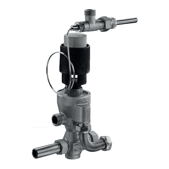
- Page 1 EB 2178 EN Translation of original instructions Type 43-8 Temperature Regulator with Hydraulic Controller Edition May 2023...
- Page 2 Note on these mounting and operating instructions These mounting and operating instructions assist you in mounting and operating the device safely. The instructions are binding for handling SAMSON devices. The images shown in these instructions are for illustration purposes only. The actual product may vary.
-
Page 3: Table Of Contents
Contents Safety instructions and measures ..............4 Notes on possible severe personal injury ............7 Notes on possible personal injury ..............7 Notes on possible property damage ..............8 Markings on the device .................9 2.1 Material identification number ..............10 Design and principle of operation ..............10 Technical data .....................11 3.1.1 Process medium and scope of application ............11 Measures for preparation ................15... -
Page 4: Safety Instructions And Measures
In case operators intend to use the devices in applications or conditions other than those specified, contact SAMSON. SAMSON does not assume any liability for damage resulting from the failure to use the de- vice for its intended purpose or for damage caused by external forces or any other external factors. - Page 5 Î Wear hearing protection when working near the valve. Follow the instructions given by the plant operator. Î Check with the plant operator for details on further protective equipment. Revisions and other modifications Revisions, conversions or other modifications of the product are not authorized by SAMSON. They are performed at the user's own risk and may lead to safety hazards, for example. Fur- thermore, the product may no longer meet the requirements for its intended use. Warning against residual hazards...
- Page 6 Start-up and shutdown procedures fall within the scope of the operator's duties and, as such, are not part of these mounting and operating instructions. SAMSON is unable to make any statements about these procedures since the operative details (e.g. differential pressures and temperatures) vary in each individual case and are only known to the operator.
-
Page 7: Notes On Possible Severe Personal Injury
Î Wear protective clothing and safety gloves. Damage to health relating to the REACH regulation. If a SAMSON device contains a substance listed as a substance of very high concern on the candidate list of the REACH regulation, this is indicated on the SAMSON deliv- ery note. Î Information on safe use of the part affected u https://www.samsongroup.com/reach-en.html. -
Page 8: Notes On Possible Property Damage
Î Do not dismantle the regulator. Î Only perform allowed activities on the regulator. Î Contact SAMSON's After-sales Service before replacing spare parts. Risk of valve damage due to contamination (e.g. solid particles) in the pipeline. The plant operator is responsible for cleaning the pipelines in the plant. -
Page 9: Markings On The Device
Specifications on the valve – 1 Date of manufacture 2 Configuration ID 2438 3 Device index PN 16 SAMSON Type 2430 Control Thermostat Specifications on the scaled cap on the adjustment knob to adjust the set point SAMSON 2750-0 1 Model number/type designation 2430... -
Page 10: Material Identification Number
3 Design and principle of tion and the heat flow is interrupted. At the operation same time, the temperature set point of the thermostat drops by approx. 8 K (optionally The Type 43-8 Regulator is used to control 15 K) to reach the reduced idle temperature. the temperature of instantaneous water heat- This prevents reheating with temperature ers in small district heating units. peaks as well as the supply lines from cool- The devices consist of the Type 2430 Control... -
Page 11: Technical Data
Design and principle of operation 3.1 Technical data 3.1.1 Process medium and scope of application The Type 43-8 Temperature Regulator is suit- able for the control of liquids in instanta- neous water heaters in small district heating units. For a temperature range from 45 to 65 °C Valve DN 15 · PN 25... - Page 12 Design and principle of operation Table 2: Technical data Type 2432 Valve Type 43-8 Type 43-8 N Valve size DN 15 coefficient Pressure rating PN 25 PN 16 Max. perm. differential pressure Δp 20 bar 6 bar Max. permissible valve temperature 130 °C 120 °C Type 2430 Control Thermostat Set point range 45 to 65 °C Capillary tube 2 m (5 m as special version) Max. perm. temperature at the sensor 30 K above the adjusted set point...
- Page 13 Stainless steel 1.4305 CW602N Valve plug 1.4104 and brass, resistant to dezincification, with EPDM soft seal Valve spring and spring in Stainless steel 1.4310 Type 2438 Baffle plate Capillary tube Copper Temperature sensor Sensor CrNiMo steel Set point adjuster PETP, glass fiber reinforced Table 4: Dimensions in mm · Weights in kg Type 43-8 Type 43-8 N Length Height Type 2432/2438/2430 kg (approx.) EB 2178 EN...
- Page 14 Design and principle of operation Dimensional drawings Ø 12 G¾ /G1 Ø 76 G¾ G¾ Ø 18 Fig. 3: Dimensional drawings for Type 43-8 and Type 43-8 N EB 2178 EN...
-
Page 15: Measures For Preparation
Report any damage to − Observe the storage instructions. SAMSON and the forwarding agent − Avoid long storage times. (refer to delivery note). − Contact SAMSON in case of different storage conditions or longer storage 4.1 Unpacking times. Note... -
Page 16: Preparation For Installation
Mounting and start-up 5 Mounting and start-up SAMSON's After-sales Service can provide NOTICE NOTICE more detailed storage instructions on re- quest. Risk of overheating due to excessive ambient temperatures or insufficient heat dissipation when components are insulated. 4.4 Preparation for installation −... -
Page 17: Mounting Positions
Mounting and start-up 5.2 Mounting positions 3. Attach the corrugated pipe (W) between the hydraulic controller and cold water Install the Type 43-8 and Type 43-8 N in a connection of the heat exchanger. Ob- horizontal position with control thermostat serve the tightening torques specified in facing upward onto the heat exchanger. - Page 18 Connections G ¾ or G 1 Heat exchanger View A Heating Cold water water return Cold Notch connection water Fig. 4: Arrangement of Type 43-8 with accessories (without circulation) Table 5: Installation dimensions · Dimensions in mm Type 43-8 43-8 N G ¾ 40 to 45 mm G 1 73 to 79 mm ≥260 mm ≥240 mm M5 grub screw...
-
Page 19: Installing The Control Thermostat
In plate heat exchangers, this location is directly upstream of the outlet where the heated wa- ter flows out of the heat exchanger. Î The notch at the end of the sensor must point upward (see Fig. 5). Hot water outlet Plate heat exchanger max. ±5° 5 mm Adapter with temperature sensor View A Temperature sensor, notch facing upward Fig. 5: Arrangement of Type 2430 Control Thermostat for Type 43-8 EB 2178 EN... -
Page 20: Additional Fittings
Mounting and start-up Î Install the sensor pocket (F) in such a way carried along by the medium. For example, that the sensor reaches horizontally into the SAMSON Type 1 NI Strainer is suitable the hot water duct. (u T 1010). Î Observe a distance of approx. 5 mm be- The following points must be observed when tween the tip of the sensor and the rear installing the strainer: of the housing. -
Page 21: Start-Up
− Allow components and pipelines to cool down or warm up to the ambient tempera- ture. − Wear protective clothing and safety gloves. Domestic hot water heated in an instantaneous heating system with Type 43-8 District heating supply Control thermostat Heat exchanger Cold water... -
Page 22: Operation
Operation 6 Operation To adjust the set point, proceed as follows: 1. Set the target temperature set point by See Fig. 2. turning the black adjustment knob (9) ac- cording to the scale (see Fig. 7). 6.1 Adjusting the set point at − Turn the adjustment knob clockwise the control thermostat () to reduce the temperature set The ambient temperature at the set point ad-... -
Page 23: Servicing
1. Put the device out of operation. See sec- tion 9.1. Note 2. Remove any residual process medium. The device was checked by SAMSON before 3. Send the device together with the filled-in it left the factory. form to your nearest SAMSON subsidi- − The product warranty becomes void if ary. - Page 24 Î Replace damaged parts. bonnet. Î Replace damaged parts. Leakage at the connection between the hydraulic controller and valve or Seal is defective Î Contact SAMSON's After-sales control thermostat. Service. Note Contact SAMSON's After-sales Service for malfunctions not listed in the table. EB 2178 EN...
-
Page 25: Decommissioning And Removal
Decommissioning and removal 9 Decommissioning and removal SAMSON's After-sales Service can support you in drawing up an inspection and test plan for your plant. DANGER Risk of bursting in pressure equipment. Valves and pipelines are pressure equip- ment. Improper opening can lead to valve components bursting. -
Page 26: Decommissioning
Decommissioning and removal 9.2 Disposal WARNING Risk of burn injuries due to hot or cold com- SAMSON is a producer registered at the following ponents and pipelines. European institution Depending on the process medium, valve u https://www.ewrn.org/ components and pipelines may get very hot national-registers/national- registers. -
Page 27: Annex
No spare parts are available for the You can reach our after-sales service at Type 43-8 and Type 43-8 N Temperature aftersalesservice@samsongroup.com. Regulators. Addresses of SAMSON AG and its subsid- iaries The addresses of SAMSON, its subsidiaries, 11 Certificates representatives and service facilities worldwide can be found on our website The EU declarations of conformity are in- (u www.samsongroup.com) or in all... - Page 28 Decommissioning and removal Modul H/Module H, Nr./No. / N° CE-0062-PED-H-SAM 001-16-DEU-rev-A SAMSON erklärt in alleiniger Verantwortung für folgende Produkte:/For the following products, SAMSON hereby declares under its sole responsibility: Ventile für Temperaturregler/Valves for temperature regulators Typ/Type 2111, 2121, 2431, 2432, 2435, 2436, 2437 (Erz.-Nr./Model No. 2710), 2433, 2118 (2713), 2119 (2803), 2111, 2121 (2811), 2114 (2814) die Konformität mit nachfolgender Anforderung/the conformity with the following requirement.
- Page 29 Decommissioning and removal Modul H/Module H, Nr./No. / N° CE-0062-PED-H-SAM 001-16-DEU-rev-A SAMSON erklärt in alleiniger Verantwortung für folgende Produkte:/For the following products, SAMSON hereby declares under its sole responsibility: Ventile für Temperaturregler/Valves for temperature regulators Typ/Type 2431, 2432, 2435, 2436, 2437 (Erz.-Nr./Model No. 2710) die Konformität mit nachfolgender Anforderung/the conformity with the following requirement.
- Page 30 EB 2178 EN...
- Page 31 EB 2178 EN...
- Page 32 EB 2178 EN SAMSON AKTIENGESELLSCHAFT Weismüllerstraße 3 · 60314 Frankfurt am Main, Germany Phone: +49 69 4009-0 · Fax: +49 69 4009-1507 samson@samsongroup.com · www.samsongroup.com...
Need help?
Do you have a question about the 43-8 and is the answer not in the manual?
Questions and answers