Samson 43-1 Mounting And Operating Instructions
Temperature regulators
Hide thumbs
Also See for 43-1:
- Mounting and operating instructions (12 pages) ,
- Mounting and operating instructions (68 pages)
Table of Contents
Advertisement
Quick Links
Advertisement
Table of Contents

Related Manuals for Samson 43-1


Summary of Contents for Samson 43-1
- Page 1 EB 2171 EN Translation of original instructions Type 43-1 · Stainless steel Type 43-2 · Spheroidal body with female thread graphite iron body with flanges Type 43-2 · Red brass with welding ends Type 43-1 and Type 43-2 Temperature Regulators Self-operated Regulators Edition August 2019...
- Page 2 Î For the safe and proper use of these instructions, read them carefully and keep them for later reference. Î If you have any questions about these instructions, contact SAMSON‘s After-sales Service Department (aftersalesservice@samson.de). The mounting and operating instructions for the devices are included in the scope of delivery.
-
Page 3: Table Of Contents
Contents Safety instructions and measures ..............5 Notes on possible severe personal injury ............9 Notes on possible personal injury ..............10 Notes on possible property damage ..............11 Markings on the device ................13 Valve nameplate ..................13 Nameplate of the control thermostat ..............14 Location of the nameplate on the valve and control thermostat ......14 Material numbers ..................15 Design and principle of operation ..............16 Technical data .....................18... - Page 4 Contents Operation ....................31 Adjusting the set point ..................31 Servicing.....................32 Cleaning and replacing the seat and plug ............34 Lubricants and sealants ................35 Tightening torques ..................35 Tools ......................35 Preparation for return shipment ..............36 Ordering spare parts and operating supplies ..........36 Malfunctions ....................36 Decommissioning and removal ..............39 10.1 Decommissioning ..................39...
-
Page 5: Safety Instructions And Measures
In case operators intend to use the regulators in other applications or conditions than specified, contact SAMSON. SAMSON does not assume any liability for damage resulting from the failure to use the de- vice for its intended purpose or for damage caused by external forces or any other external factors. - Page 6 Î Observe safety measures for handling the device as well as fire prevention and explosion protection measures. Safety features The Types 43-1 and 43-2 Regulator do not have any special safety equipment. When re- lieved of pressure, the regulators are opened by the force of the internal plug springs. EB 2171 EN...
- Page 7 Safety instructions and measures Responsibilities of the operator The operator is responsible for proper operation and compliance with the safety regulations. Operators are obliged to provide these mounting and operating instructions as well as the referenced documents to the operating personnel and to instruct them in proper operation. Furthermore, the operator must ensure that operating personnel or third persons are not ex- posed to any danger.
- Page 8 Safety instructions and measures Referenced documentation The following documents apply in addition to these mounting and operating instructions: Mounting and operating instructions for – e.g. Type 2430 Control Thermostat u EB 2430 e.g. Type 2430 Control Thermostat (vapor pressure) u EB 2430-3 e.g. Type 2403 Safety Temperature Monitor (STM) u EB 2183 Type 2439 Safety Temperature Limiter (STL) e.g.
-
Page 9: Notes On Possible Severe Personal Injury
Safety instructions and measures 1.1 Notes on possible severe personal injury DANGER Risk of bursting in the regulator. Regulators and pipelines are pressure equipment. Improper opening can lead to com- ponents bursting. Î Before starting any work on the regulator, depressurize all plant sections affected as well as the regulator. -
Page 10: Notes On Possible Personal Injury
WARNING Damage to health relating to the REACH regulation. If a SAMSON device contains a substance which is listed as being a substance of very high concern on the candidate list of the REACH regulation, this circumstance is indi- cated on the SAMSON delivery note. -
Page 11: Notes On Possible Property Damage
The lubricants to be used depend on the regulator material. Unsuitable lubricants may corrode and damage the surface. Î Only use lubricants approved by SAMSON. When in doubt, consult SAMSON. Risk of leakage and regulator damage due to excessively high or low tightening torques. - Page 12 Î Do not dismantle the regulator. Î Only perform allowed activities on the regulator. Î Contact SAMSON's After-sales Service department before replacing spare parts. Note SAMSON's After-sales Service can support you concerning lubricant, tightening torques and tools approved by SAMSON.
-
Page 13: Markings On The Device
Markings on the device 2 Markings on the device 2.1 Valve nameplate Body made of red brass or spheroidal graphite iron 1 Type designation SAMSON 2 Model number 3 Configuration ID 4 Order number or year of manufacture ) coefficient 6 Perm. -
Page 14: Nameplate Of The Control Thermostat
Markings on the device 2.2 Nameplate of the control thermostat 1 Model number 2004 2 Type designation 0062 3 Configuration ID 4 CE marking 5 Temperature range in °C and °F Register number (type test according to DIN EN 14597) Fig. 2: Nameplate of the control thermostat 2.3 Location of the nameplate on the valve and control thermostat Type 2431/2432 (red brass) Type 2432 (stainless steel) -
Page 15: Material Numbers
Markings on the device 2.4 Material numbers The material of the Type 2431 and Type 2432 Valves is indicated on the cast body. Specifying the configuration ID, you can contact us to find out more details. The 3 is specified on the nameplate (Configuration ID). -
Page 16: Design And Principle Of Operation
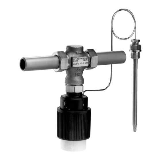
(5). As a result, the temperature set ation point is changed. Î See Fig. 4. The Type 43-1 and Type 43-2 Regulators are The Type 43-1 (or Type 43-2) Regulator con- suitable for plants to be heated. sists of a Type 2431 (or Type 2432) Globe The valves close when the temperature rises. - Page 17 Design and principle of operation Type 43-2 Type 43-1 Type 2432 Valve (male thread) Type 2431 Valve (female thread) Legend Valve body Connection nut with seal and welding end Seat Plug balanced by a piston Plug stem Valve spring Set point spring Set point adjuster...
-
Page 18: Technical Data
Process medium and scope of application Noise emission Temperature regulators for district heating systems, heat generators, heat exchangers SAMSON is unable to make general state- and other HVAC and industrial applications. ments about noise emissions. The noise emis- The Type 43-1 and Type 43-2 Temperature... - Page 19 Design and principle of operation Table 1: Technical data · All pressures in bar (gauge) Type 2431 and Type 2432 Valves Valve size G ½ to G 1 · DN 15 to 25 DN 32 to 50 Pressure rating PN 25 Max. perm. differential pressure ∆p 20 bar 12 bar Max. perm. valve temperature 150 °C Metal seal: leakage class I (≤0.05 % of K coefficient)
- Page 20 Thermowell Copper or stainless steel 1.4310 Type 43-2 with flanged body valve (DIN only) For Type 43-1 and Type 43-2 with flanged valve body For oils (ASTM I, II, III): FKM soft seal Table 4: Dimensions in mm and weights in kg Type 2431 Valve (female thread) Valve size G ½...
- Page 21 Design and principle of operation Table 4: Dimensions in mm and weights in kg Type 2432 Valve (male thread) Valve size DN 15 DN 20 DN 25 DN 32 DN 40 DN 50 Length L Height H2 Connection R G ¾ G 1 G 1¼ G 1¾ G 2 G 2½ Type 43-2 Valve · Welding ends · Threaded ends Length L1 for welding ends Length L2 for threaded ends Height H...
- Page 22 Design and principle of operation Dimensional drawings G ½ (G ¾) Ø12 (19) Ø9.5 (16) Thermowell Packing Type 43-2 Type 43-1 Type 43-2 Valve with male thread and control thermostat Female thread (red brass) Flanged valve body (spheroidal graphite iron) Ød Type 43-2 Type 43-2 Type 43-1...
-
Page 23: Measures For Preparation
2. Check the shipment for transportation ences (e.g. impact). damage. Report any damage to Do not damage the corrosion protection – SAMSON and the forwarding agent (paint, surface coatings). Repair any (refer to delivery note). damage immediately. 4.1 Unpacking Protect the device against moisture and –... -
Page 24: Storage
Risk of regulator damage due to improper quest. storage. − Observe the storage instructions. − Avoid long storage times. − Contact SAMSON in case of different stor- age conditions or long storage periods. Note We recommend regularly checking the de- vice and the prevailing storage conditions during long storage periods. -
Page 25: Mounting And Assembly
− Do not attach supports directly to the valve medium may impair the proper functioning or control thermostat. of the regulator. We recommend installing a strainer (e.g. SAMSON Type 1 NI) upstream of the pressure reducing valve (see sec- tion 6.3.1). Î Check the valve and control thermostat to make sure that they are clean and not damaged. -
Page 26: Mounting Positions
Mounting and start-up 6.1 Mounting positions 6.2 Temperature sensor Î See Fig. 6 Standard mounting position Types 43-1 and 43-2 can be mounted in NOTICE any position when the medium temperature Galvanic corrosion due to incorrectly se- is between –20 and +80 °C. -
Page 27: Dynamic Behavior Of Type 2430 Control Thermostat
Mounting and start-up 6.2.1 Dynamic behavior of 6.2.3 Capillary tube Type 2430 Control Ther- Carefully run the capillary tube without mostat bending or twisting it. Avoid locations with considerable ambient temperature fluctua- The dynamics of the regulator are mainly de- tions along the entire length of the tube. termined by the response of the sensor with its characteristic time constant. -
Page 28: Additional Fittings
For example, the SAMSON Type 1 NI Strainer is suitable 6.3.3 Thermometer (u T 1010). Install a thermometer (4) both upstream and... - Page 29 Mounting and start-up Shut-off valve Temperature regulator Temperature sensor Strainer Thermometer Shut-off valve Fig. 6: Installation example · Type 43-1 on a water-heated boiler Table 6: Inlet and outlet lengths min. min. a x DN b x DN Inlet length Outlet length State of process...
-
Page 30: Pipeline Flushing
Î Open the shut-off valves (1, 6) slowly The plant operator is responsible for preferably starting from the upstream performing the pressure test. SAMSON's pressure side. After-sales Service can support you to plan and perform a pressure test for your plant. -
Page 31: Operation
Î Turn the set point adjuster counterclock- wise () to reduce the temperature set point. Type 43-1/43-2 Set point ranges for DN 15 to 25 Set point ranges for DN 32 to 50 with sensor Ø 9.5 mm with sensor Ø... -
Page 32: Servicing
Operation 8 Servicing Table 7: Set point ranges Set point Set point change Sensor Ø The regulator does not require any mainte- range in °C per turn nance. Nevertheless, it is subject to natural 2.5 °C 9.5 mm wear, particularly at the seat, plug and con- 0 to 35 °C 2 °C 16 mm... - Page 33 − Wear protective clothing and safety gloves. The regulator was checked by SAMSON before it left the factory. − Certain test results certified by SAMSON NOTICE lose their validity when the valve is Risk of valve damage due to incorrect servic- opened.
-
Page 34: Cleaning And Replacing The Seat And Plug
2. Renew the seal (3.2) and insert it into the body. Note 3. DN 15 to 25 SAMSON's After-sales Service can support you concerning lubricant, tightening torques Screw in the plug (3) using the plug and tools approved by SAMSON. wrench. Observe the tightening torques specified in section 8.3. -
Page 35: Lubricants And Sealants
Servicing 8.2 Lubricants and sealants Note SAMSON's After-sales Service can support you concerning lubricants and sealants approved by SAMSON. 8.3 Tightening torques Component Valve size Tightening torque in Nm G ½ to G 1 · DN 15 to 25 ½ NPT to 1 NPT · NPS ½ to 1 Seat (2) DN 32 to 50... -
Page 36: Preparation For Return Shipment
Defective devices can be returned to sizing. In the simplest case, the functioning SAMSON for repair. Proceed as follows to can be restored following the recommended return devices to SAMSON: action. Special tools may be required for re- 1. - Page 37 Recommended action Î Clean the seat and plug. Seat and plug are worn or leak. Î Replace the damaged seat and plug. Î Contact SAMSON's After-sales Service. Î Remove foreign particles. Foreign particles blocking the plug Î Replace damaged parts.
- Page 38 Regulator or K coefficient too small install a different sized regulator. Î Contact SAMSON's After-sales Service. A safety device (e.g. STL or STM) has been Î Check plant. Unlock safety device (where Temperature at the triggered.
-
Page 39: Decommissioning And Removal
Regulator components and the pipeline may 11.1 After-sales service become very hot or cold. Risk of burn inju- ries. Contact SAMSON's after-sales service for − Allow components and pipelines to cool support concerning service or repair work or down or heat up. - Page 40 Appendix E-mail address You can reach our after-sales service at aftersalesservice@samson.de. Addresses of SAMSON AG and its subsid- iaries The addresses of SAMSON, its subsidiaries, representatives and service facilities world- wide can be found on our website (u www.samson.de) or in all SAMSON product catalogs.
-
Page 41: Spare Parts
Appendix 11.2 Spare parts DN 15 to 25 DN 32 to 50 Valve body Seat Plug 3.1 Plug assembly (DN 32 to 50) 3.2 Seal 11.3 Certificates The EU declarations of conformity are included on the next pages. EB 2171 EN... - Page 42 Modul H/Module H, Nr./No. / N° CE-0062-PED-H-SAM 001-16-DEU-rev-A SAMSON erklärt in alleiniger Verantwortung für folgende Produkte:/For the following products, SAMSON hereby declares under its sole responsibility: Ventile für Temperaturregler/Valves for temperature regulators Typ/Type 2431, 2432, 2435, 2436, 2437 (Erz.-Nr./Model No. 2710) die Konformität mit nachfolgender Anforderung/the conformity with the following requirement.
- Page 43 Modul H/Module H, Nr./No. / N° CE-0062-PED-H-SAM 001-16-DEU-rev-A SAMSON erklärt in alleiniger Verantwortung für folgende Produkte:/For the following products, SAMSON hereby declares under its sole responsibility: Ventile für Temperaturregler/Valves for temperature regulators Typ/Type 2111, 2121, 2431, 2432, 2435, 2436, 2437 (Erz.-Nr./Model No. 2710), 2433, 2118 (2713), 2119 (2803), 2111, 2121 (2811), 2114 (2814) die Konformität mit nachfolgender Anforderung/the conformity with the following requirement.
- Page 44 EB 2171 EN SAMSON AKTIENGESELLSCHAFT Weismüllerstraße 3 · 60314 Frankfurt am Main, Germany Phone: +49 69 4009-0 · Fax: +49 69 4009-1507 samson@samson.de · www.samson.de...
Need help?
Do you have a question about the 43-1 and is the answer not in the manual?
Questions and answers