Table of Contents
Advertisement
Quick Links
PASSIVE INFRARED LONG
1 General Information
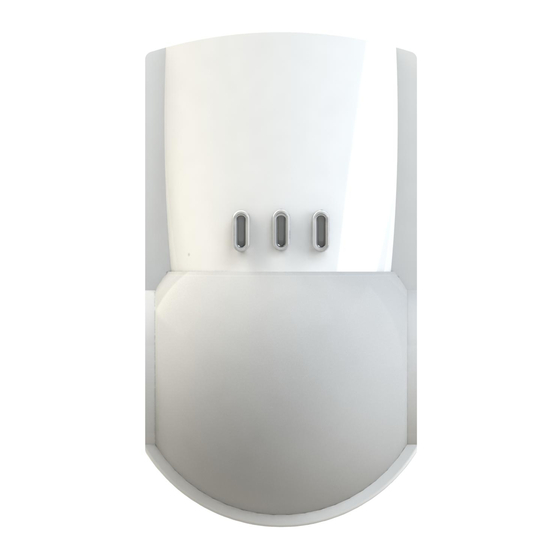
1.1 Passive infrared long range detector «Foton-16» (hereinafter, the
Detector) is designed for detecting intrusion into a protected space
and generating an alarm message.
1.2 Ambient class: Boreal climate.
1.3 The Detector is designed to operate continuously around the
clock.
1.4 The Detector does not produce any interferences to other
detectors of the same or other type and designation, as well as to any
domestic radio equipment.
2 Features
- Active infrared channel with antimasking function.
- Possibility of saving of the Detection channel masking parameters
into nonvolatile memory.
- Two-color LED indication with a possibility of it's disabling.
- Self-testing mode.
- Immunity to insect's intrusion to the pyrodetector.
- Swivel bracket (supplied) providing ease of the Detector installation
and detection zone repositioning.
3 Specifications
Parameter
Detection range, maximum
Maximum antimasking detection range, not less than
Power supply
Consumption current, not more than
Alarm message duration, not less than
Operation temperature
Relative humidity under +25 °С without moisture
condensation, up to
IP rating
Dimensions, maximum
Mass, maximum
Average service life, not less than
Detection zone pattern is shown in Figure 1.
Figure 1 – Detection Zone Pattern
4 Scope of delivery
Name
Passive infrared long range detector «Foton-16A»
Swivel bracket
Screw 3-3х30.016
Passive infrared long range detector «Foton-16A».
Installation Guide
5 Installing the Detector
Recommended mounting height of the Detector is 2.3 m above the
floor. The shape of the Detector base allows to mount the Detector
on the wall, as well as in the corner of the room. In case of the swivel
bracket usage (supplied), the Detector can be installed on the wall or
ceiling at a hight 2.3 ... 3 m above the floor. Swivel bracket construction
provides detection zone repositioning.
RANGE DETECTOR
«FOTON-16A»
WITH ANTIMASKING
FUNCTION
Installation Guide
Value
20 m
0.1 m
9 ...15 V DC
35 mA
4 sec
minus 30 ... +55 °С
98 %
IP41
126 х 70 х 55 mm
150 g
8 years
20 m
20 m
When choosing the Detector installation place, take note of the fact
that the detection zone may be limited by non-transparent objects
(curtains, houseplants, cabinets, bookcases, etc.), as well as glass and
mesh partitions. There must be no windows, air conditioners, space
heaters or heating radiators in the Detector visibility range.
The Detector installation:
5.1 Unfasten the latch through the opening (5), which is situated
downside the detector case by means of screwdriver and put off the
detector cover.
5.2 Put off the PCB by means of pushing up it's fixing arm (4) on
the base.
5.3 Drill the holes (1) for wiring and fastening the Detector:
- for wall mounting – holes (6);
- for corner mounting – holes (3).
5.4 Pass the wire through the mounting holes (1) and fasten the
base on the wall (corner) by screws.
5.5 If swivel braket is used for installation:
- open hole (2);
- insert a nut (8) to the sphere bulge (9);
- insert a sphere (9) and then a bush (7) to the base of the swivel
bracket (11).
Fasten an assembled swivel bracket on the wall (ceiling) by screws.
Pass the wires and tighten the base on the swivel bracket by the screw
(12). Fix position of the sphere when tightening the screw (12).
5.6 Put PCB on it's place.
1
3
6
a) Detector base
Note – Places for mounting holes on the installation surface can
be marked using a detector base with opened holes as a pattern.
6 The Detector Hooking up
Marked terminals for the Detector hooking up are located at the top
of the PCB (See Figure 3).
a) Side
View
FAILURE
Figure 3 – Terminals for hookup wire connection
Connection of the Detector to the control panel (CP) should be
b) Top
fulfilled in accordance with CH Installation Guide.
View
7 The Detector Adjustment
The Detector adjustment should be realized by changing position
of «1», «2», «3», «4» and «5» DIP-switches, located at the top of
PCB. DIP-switch «1» changes sensitivity value, «5» – manages
anti-masking channel operation tactics, «2», «3», «4» supervise only
the LED indication modes.
QNT
1 pc.
1 pc.
2 pcs.
1 copy
MASK
MEM
IND
TEST
SENS
7
2
3
4
b) Swivel Bracket
5
Figure 2 – Detectoir Base and Swivel Bracket
AL
TAMPER
Table 2
DIP-switch
«1»
Sensitivity
«2»
TEST
«3»
LED indication
«4»
Alarm memory
«5»
MASK
8 9
10
11
12
+
12V-
Position
ON
OFF
Norm
High
Alarm LED
Indication of
Indication
detection
ON
OFF
ON
OFF
See Cl. 8.7
Advertisement
Table of Contents

Summary of Contents for Rielta FOTON-16A
- Page 1 Figure 1 – Detection Zone Pattern anti-masking channel operation tactics, «2», «3», «4» supervise only the LED indication modes. 4 Scope of delivery Table 2 Name Position Passive infrared long range detector «Foton-16A» 1 pc. DIP-switch Swivel bracket 1 pc. Screw 3-3х30.016 2 pcs.
- Page 2 («ON» position) to high («OFF» position). Detection range data in and classified as fit for operation and packed by «RIELTA» JSC. Cl. 3 are reported for the Detector normal sensitivity state. 8.6 Self-Testing...


Need help?
Do you have a question about the FOTON-16A and is the answer not in the manual?
Questions and answers