Advertisement
Quick Links
1 Introduction
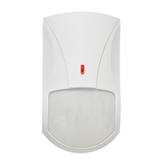
The detector «Foton-10B» (hereinafter, the detector) is designed for
detecting intrusion into the protected space and generating an alarm
message by opening the relay output contacts.
The detector ensures tamper protection. The «Tamper» message is
generated by opening microswitch contacts.
The detector is resistant to the exposure of ambient light and radio
interference, as well as to influence of small pets: mice, rats, birds,
placed in the cages at a distance not less than 2.5 m.
2 Features
- Dual-element pyrodetector.
- Spherical Fresnel lens.
- Vertical curtain detection zone.
- Immunity to insects intrusion to the pyrodetector.
- Microprocessor-based signal processing.
- Selectable modes of testing, sensitivity, alarm memory and led
indication.
- Self-test mode.
- The detector is rated for switching to the DC power source with
output voltage 9 – 15 V.
- Possibility to install the detector on the swivel bracket (supplied)
for the detection zone repositioning.
- Case tamper protection.
3 Specifications
Table 1
Parameter
Detection zone
Power supply, V DC
Tamper output contacts
Alarm message duration
Detection zones
Sensitivity
Operating temperature range
Relative humidity
IP rating
Dimensions, max
Weight, max
Detection zone pattern is shown in Figure 1.
5 m
2.3 m
1 m
0
1 m
Figure 1 – Detection zone pattern
4 Application
The detector can be installed for protection of window openings
and rooms in the flats, shops, offices, museums.
PASSIVE INFRARED
DETECTOR
«FOTON-10B»
Installation Guide
Value
Up to 10 m
9 – 15 V, current 15 mА
Closed – «Norm» message, current
30 mА, voltage 72 V
Not less than 2 sec
1 long-range
Chosen by switch «1» (position 1/2)
minus 30 ... + 55
98 % under 25
0
С without moisture
condensation
IP41
126 х 70 х 55 mm
110 g
Detection zone
10 m
structure
10 m
5 Scope of Delivery
Each Detector unit package contains the items listed in Table 2.
Table 2
Passive infrared detector «Foton-10B»
Swivel bracket
Screw 3-3х30.016
Passive infrared detector «Foton-10B». Installation Guide
6 Choosing the Place of Installation
The detector is designed for operation in the closed areas. When
choosing the detector installation place, take note of the fact that the
detection zone may be limited by non-transparent objects (curtains,
houseplants, cabinets, bookcases, etc), as well as glass and mesh
partitions. There must be no windows, air conditioners, space heaters
or heating radiators in the detector visibility range.
Recommended installation height:
- without swivel bracket – 2 – 3 m;
- by means of swivel bracket – 2.3 – 3 m (on condition that the
detector tilt is adjusted).
Power supply and alarm loop wires should be located far enough
from power feed cables.
7 The Detector Installation
- Unfasten the latch through the opening, which is situated downside
the detector case by means of screwdriver and put off the detector
cover (Figure 2).
- When installing the detector without swivel bracket it is necessary
to put off the PCB by means of pushing up it's fixing arm.
Swivel Bracket Components
Plug
Sphere
Screw
Wall Mounting
Ceiling Mounting
0
С
- Drill the holes in the base of the detector for wiring and fastening
the detector (Figure 2).
- Choose the place of installation, mark the places for mounting
holes with the regard to detector base (or swivel bracket) openings,
drill the holes in the wall.
- Pass the wire through the mounting holes in the base, leave several
centimeters of installation wire for it's fastening inside the case.
- Fix the base of the detector case on the wall (swivel bracket) at
the chosen place. In case of swivel bracket using, unscrew the cap
screw from the swivel bracket sphere. Fit the square bulge of the
swivel bracket external sphere with the corresponded opening on
the detector base. Plug in the screw to the opening in the top of the
detector base and fix the connection by the screw.
- Put PCB on it's place.
8 Connection
- The terminals for the detector connection are located at the top
of PCB.
- Fulfill connections in accordance with the Figure 3a (for single
alarm loop connection) and with Figure 3b (with alarm loop and
tamper connection).
- Install the DIP-switches in accordance with application conditions.
Name
For corner
mounting
Swivel
bracket
For the wall
mounting
Opening for the
cover latch
Figure 2 – The Detector Base and the Swivel Bracket
QNT
1 pc.
1 pc.
2 pcs.
1 copy
Detector Base
For fastening the base
To the swivel bracket
Port plug
PCB fixing arm
Advertisement

Related Manuals for Rielta FOTON-10B


Summary of Contents for Rielta FOTON-10B
- Page 1 1 Introduction houseplants, cabinets, bookcases, etc), as well as glass and mesh The detector «Foton-10B» (hereinafter, the detector) is designed for partitions. There must be no windows, air conditioners, space heaters detecting intrusion into the protected space and generating an alarm or heating radiators in the detector visibility range.
- Page 2 If DIP-switch is in position «3» – «IND», manufactured in accordance with current technical documentation generation of alarm message is displayed by LED-indicator lighting is classified as fit for operation and is packed by «RIELTA» JSC. for the 3 sec period. 2) Sensitivity mode adjustment DIP-switches position: «2»...
Need help?
Do you have a question about the FOTON-10B and is the answer not in the manual?
Questions and answers