Advertisement
Quick Links
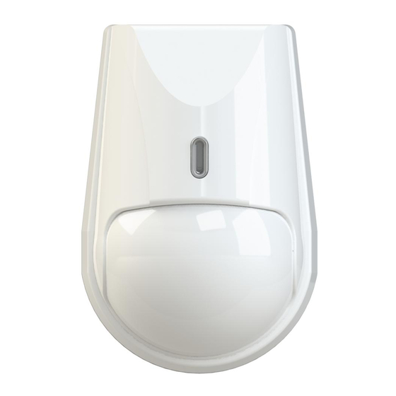
PASSIVE INFRARED
1 General Information
1.1 Passive infrared detector «Foton-10MD» (hereinafter, the detector)
is designed for detecting intrusion into a protected space and generating
an alarm message by opening relay output contacts.
1.2 The detector is resistant to influence of small pets: mice, rats,
birds, as well as to the exposure of ambient light and radio interference,
slow temperature changes, convective airflow, power supply voltage
pulses, electrostatic discharge, VHF electromagnetic field.
1.3 The detector ensures false alarm absence in case of movement
on the floor of small pets with weight up to 10 kg (cats and fancy-breed
dogs), in case the detector installation height is not less than 2.3 m.
1.4 The detector comprices two-color LED indicator for it's operability
control, microswitch (tamper contact) for tampering detection and
DIP-switch, providing testing and alrm memory modes setting, as well
as indicator disabling.
The detector generates the following messages:
- «Norm» (Normal state of the detector) – by the relay contacts closing
repeated by red LED indicator switching off;
- «Alarm» – by the relay contacts opening repeated by LED indicator
lighting red;
- «Tamper» (unauthorized access into a case) – by microswitch
contacts opening when the detector is tampered;
- «Warm-up Time» (technical availability) – by relay contacts
opening repeated by LED indicator blinking red during one minute after
the detector energizing;
- «Alarm Memory» – is displayed by a green LED indicator lighting
during 15 min in 5 min after «Alarm» message generation.
1.5 The detector is designed to operate continuously around the clock.
2. Features
–Dual-element pyrodetector.
- Spherical Fresnel lens.
- Wide angle detection zone.
- Immunity to insect's intrusion to the pyrodetector.
- Microprocessor-based signal processing.
- The following adjustable modes: testing, sensitivity, alarm memory
and led indication.
- Self-test mode.
- Is rated for switching to the DC power source with output voltage
10 – 15 V.
- Case tamper protection.
3 Specifications
Table 1
Parameter
Maximum detection range
Power supply, V DC
Tamper output contacts
Alarm message duration, not less than
Recommended mounting height
Operating temperature
Relative humidity under 25 °С without
moisture condensation
IP rating
Dimensions, maximum
Mass, not more
Average service life, not less than
4 Scope of delivery
Each detector unit package contains the items listed in Table 2.
Table 2
Name
Passive infrared detector «Foton-10MD»
Swivel bracket
Screw 3-3х30.016
Passive infrared detector «Foton-10MD». Installation Guide
DETECTOR
«FOTON-10MD»
Installation Guide
Value
12 m
10 – 15 V, current 15 mА
Closed – «Norm» message,
current 30 mА, voltage 72 V
2 sec
2.3 m
minus 30 ... +50
95 %
IP41
90 х 60 х 50 mm
60 g
8 years
5 Choosing the Place of Installation
The detector is designed for operation in the closed areas. When
choosing the detector installation place, take note of the fact that the
detection zone may be limited by non-transparent objects (curtains,
houseplants, cabinets, bookcases, etc.), as well as glass and mesh
partitions. There must be no windows, air conditioners, space heaters
or heating radiators in the detector visibility range.
The presence in the detection area of furniture items that an animal
can get on, can lead to false alarms.
Power supply and alarm loop wires should be located far enough
from power feed cables.
6 Detection zone pattern
Top view
0
7 Installation
Before installation of the detector put off the cover and the PCB. For
this purpose act as follows:
- unfasten the latch through the opening, which is situated downside
the detector case by means of screwdriver and put off the detector
cover (Figure 2);
- when installing the detector without swivel bracket, it is necessary
to put off the PCB by means of pushing up it's fixing arm;
Ceiling
Mounting
Wall Mounting
L
о
С
- drill the holes in the base of the detector for wiring and fastening
the detector (Figure 2);
– choose the place of installation, mark the places for mounting holes
with the regard to detector base (or swivel bracket) openings, drill the
holes in the wall;
– pass the wire through the mounting holes in the base. Leave several
centimeters of installation wire for it's connection to the terminals;
- fix the base of the detector case on the wall at the chosen place;
- put the PCB on it's place (if it was put off).
Note
1 In case of swivel bracket using, turn out the cap screw M3x20 from
the swivel bracket sphere. Holding the assembled swivel bracket, fit the
QNT
square bulge of the swivel bracket external sphere with the corresponded
opening on the detector base. Turn the detector base to the left full
1 pc.
point and then to the right. Plug in the screw into the opening in the top
1 pc.
of the detector base and fix connection by the screw. Set the detector
2 pcs.
base to the operating position and fasten it by a cap screw M3x20.
1 copy
2 To ensure the best result in immunity to pets movement, it is
recommended to mount the detector without any inclination.
Side view
2.3 m
0
12 m
Figure 1
Detector Base
For the wall
mounting
For corner
mounting
Opening for the
cover latch
Swivel Bracket Components
Swivel
External
Fastening
bracket base
sphere
screw
Figure 2 – Detector base and swivel bracket
12 m
Port plug
For fastening
the base
To the swivel
bracket
PCB fixing
arm
Latch
Nut
Internal
sphere
Advertisement

Related Manuals for Rielta FOTON-10MD


Summary of Contents for Rielta FOTON-10MD
- Page 1 Power supply and alarm loop wires should be located far enough from power feed cables. 1 General Information 6 Detection zone pattern 1.1 Passive infrared detector «Foton-10MD» (hereinafter, the detector) Top view Side view is designed for detecting intrusion into a protected space and generating an alarm message by opening relay output contacts.
- Page 2 Detection zone position location is classified as fit for operation and is packed by «RIELTA» JSC. DIP-switches position: «1» – «OFF», «2» – «ON». This mode is intended for each beam of detection zone positioning in the secured Person responsible for acceptance and packing premises.
Need help?
Do you have a question about the FOTON-10MD and is the answer not in the manual?
Questions and answers