Advertisement
Quick Links
1 General Information
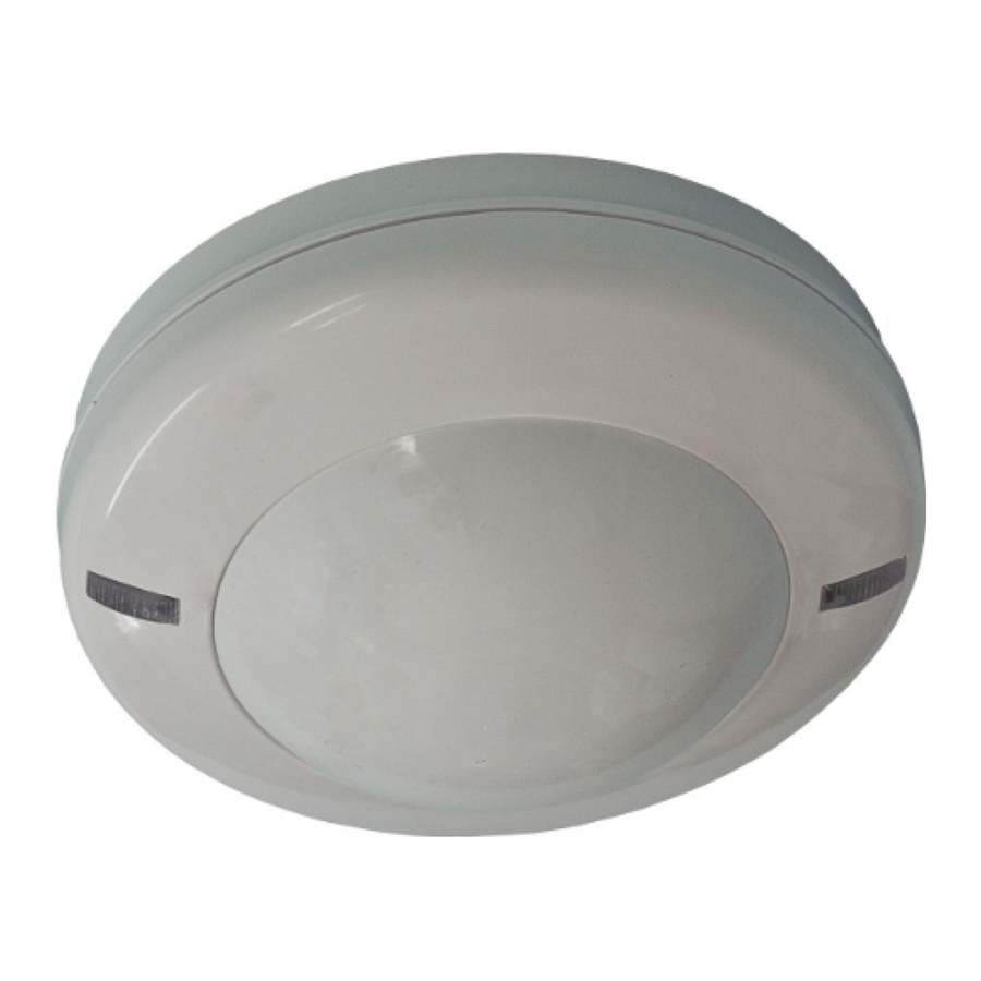
Passive infrared detector «Foton-21» (hereinafter, the Detector) is intended
for detecting intrusion into a closed protected space and generating an alarm
message by relay output contacts opening.
The Detector ensures tamper protection by means of «Tamper» microswitch
relay contacts opening.
The Detector is resistant to the ambient light impact and radio interference.
The Detector ensures absence of false alarms cased by movement of small
animals: mice, rats, birds in cages at a distance to them not less than 2.5 m.
The Detector is distinct in: attractive design, ease of installation and
maintenance.
2 Features
- The Detector is designed for ceiling mounting.
- Sensing elements – two dual-element pyrodetectors.
- Digital temperature compensation.
- Unique lens provides wide-range detection zone with high filled density,
ensuring reliable detection of the intrusion in any direction.
- Protection against intrusion of insects to a pyrodetector.
- Microprocessor-based signal processing.
- Choosing of installation height as well as the following modes: testing, alarm
memory, and LED indication.
- Self-test mode ensuranse.
- The Detector is supplied from DС current supply unit with output voltage
(9 ... 15) V.
3 Specifications
Table 1
Parameter
Detection zone diameter at mounting height:
5 m, not less than
2.5 m, not less than
Power supply
Output relay contacts
Alarm message duration, not less than
Detection zone
Detection range at the installation height
5 m and 2.5 m
Operating temperature
Relative humidity at 25 °С without moisture
condensation
IP Rating
Dimensions (diameter х height), not more than
Weight, not more than
Detection zone pattern is shown in Figure 1.
Figure 1 – Detection zone pattern
Ambient class: Boreal Climate (background temperature 15 – 35
humidity 25 – 75 %, air-pressure 86 – 106 kPa), permissible relative humidity
at +25 °С without moisture condensation.
4 Scope of Delivery
Each Detector unit package contains the items listed in Table 2.
Table 2
Name
Passive infrared detector «Foton-21»
Passive infrared detector «Foton-21». Installation Guide
5 Field of Application
The Detector can be applied in flats, shops, offices, museums, industrial
facilities.
6 Choosing the Installation Place
The Detector is designed for operation in heated closed premises.
PASSIVE INFRARED
DETECTOR
«FOTON-21»
Installation Guide
Value
9 m
4.5 m
9...15 V DC, current 17 mА
Energized Form A (NC) relay, max.
current 30 mА, voltage 72 V
2 sec
Wide-angle, cone-shaped.
Zones: 10 long-range, 1 middle-range,
1 short-range
Is chosen by «1» DIP-switch
minus 40 ... +50 °С
95 %
IP41
105 х 45 mm
100 g
5 m
9 m
10 m
о
QNT.
1 pc.
1 copy
When choosing the Detector installation place, it is advisable to take note
of the fact that the detection zone may be limited by non-transparent objects
(curtains, houseplants, cabinets, bookcases, etc.), as well as by glass and mesh
partitions. There must be no windows, air conditioners, space heaters or heating
radiators in the PIR-detection zone.
The Detector wires should be laid far enough from power supply cables.
7 Installation of the Detector
- Put off the Detector cover by it's turning counter-clockwise until tight to the
recess on the external ring of the Detector base and then rise the cover (Figure 2).
Latch
Openable holes for the
base fastening
- Put off the printed circuit board (PCB) by unfastening the latch, located
on the base.
- Drill the holes in the base (See Figure 3) for the Detector wiring and
fastening the base.
- Choose the place of installation, mark the places for mounting holes with
regard to the openings on the Detector base, drill holes in the place of installation.
- Insert wires into the hole in the base leaving several centimeters for fixation
inside the case and connection to the leading-in sockets.
- Fix the base of the detector on the chosen place.
- Set down PCB on their places.
8 Connection
- Leading-in sockets for the Detector connection are located on the PCB.
- Fulfill connections in accordance with Figure 3а (for hooking up to single
AL) or Figure 3b (to single tamper control AL).
- Set up the DIP-switches «1», «2», «3», «4» in accordance with particular
application conditions and Cl.9 of herein Installation Guide.
- Install the Detector cover on it's place. For this purpose insert the bulge
to the recess on the base external ring, push the cover and turn it in clockwise
Detector
Cont.
Circuit
1
+12V
2
-12V
3
4
5
Taper
6
Taper
9 DIP-switches Positions
Table 2
Mode
Installation height
Detection zone
testing (sizing)
Alarm indication
Alarm memory
С, relative
10 LED Indication
Two-color LEDs on the front cover are used for the Detector state displaying.
Table 3
Message
«Warm-up time»
«Norm»
«Alarm»
«Failure»
«Alarm Memory»
Detection zone
positioning
Base
Recess
Bulge
Port plugs for wiring
Figure 2 – Base and cover of the Detector
Detector
Cont.
To power
1
source
2
AL
3
AL
4
To CP
5
R
term1
6
а)
Figure 3
DIP-switch
«1»
«5 m»
«ZONE»
«2»
Testing
«IND»
«3»
is ON
«MEM»
«4»
is ON
LED Color
Blinking at a frequency 1 Hz during 55 sec after
red
-
red
Indication is ON during 3 sec
Single three-shot switching with a period of
green
3 sec in accordance with Cl. 15
LED indication is ON in 5 min.after «Alarm»
green
Switching for 0.25 sec under crossing of each
red
ray of the DZ. Mode duration is 5 min after
Cover
Circuit
+12V
To power
-12V
supply unit
AL
Security
R
AL
AL
term1
Taper-
Taper
R
control
Taper
term1
AL
b)
DIP-switch position
ON
OFF
«2.5 m»
«ALARM»
Normal operation
«OFF»
is OFF
«OFF»
is disabled
LED State
energizing
Indication is OFF
message for 15 min
warm-up time
Advertisement

Related Manuals for Rielta FOTON-21


Summary of Contents for Rielta FOTON-21
- Page 1 1 General Information Latch Bulge Passive infrared detector «Foton-21» (hereinafter, the Detector) is intended for detecting intrusion into a closed protected space and generating an alarm message by relay output contacts opening. The Detector ensures tamper protection by means of «Tamper» microswitch relay contacts opening.
- Page 2 DIP switches position: «3» – ON, «2» – OFF. This mode is intended for the and classified as fit for operation and packed by «RIELTA» JSC. Detector sensitivity appraisal (the distance inside the detection zone, which is covered before alarm message generation).
Need help?
Do you have a question about the FOTON-21 and is the answer not in the manual?
Questions and answers