Table of Contents
Advertisement
Quick Links
Advertisement
Table of Contents

Related Manuals for HP Aruba 7010 Series


Summary of Contents for HP Aruba 7010 Series
- Page 1 Aruba 7010 Series Controller...
- Page 2 US $10.00 to: Hewlett-Packard Enterprise Company Attn: General Counsel 3000 Hanover Street Palo Alto, CA 94304 www.arubanetworks.com 1344 Crossman Avenue Sunnyvale, California 94089 Phone: 408.227.4500 Fax 408.227.4550 Aruba 7010 Series Controller | Installation Guide 0511516-03 | August 2015...
-
Page 3: Table Of Contents
Removing an SFP ..................... 23 Connecting an LC Fiber Optic Cable .............. 23 Specifications, Safety, and Compliance .......... 25 7010 Specifications....................25 Physical ......................25 Power Supply Specifications................25 Operating Specifications .................25 Storage Specifications ..................25 | Installation Guide Aruba 7010 Series Controller... - Page 4 Taiwan (BSMI) ....................27 Regulatory Model Name .................27 Proper Disposal of Aruba Equipment ..............27 Waste of Electrical and Electronic Equipment..........27 European Union RoHS..................27 India RoHS ......................27 China RoHS ....................... 27 | Installation Guide Aruba 7010 Series Controller...
-
Page 5: Preface
The latest ArubaOS User Guide and ArubaOS CLI Reference Guide are required for the complete management of an Aruba controller. The latest documentation and the translation of this document into other languages can be found at www.arubanetworks.com/documentation. | Installation Guide Preface | Aruba 7010 Series Controller... -
Page 6: Contacting Support
Software Licensing Site licensing.arubanetworks.com End of Support information http://www.arubanetworks.com/support-services/end-of-life- products/end-of-life-policy/ Security Incident Response Team (SIRT) http://www.arubanetworks.com/support-services/security- bulletins/ Support Email Addresses Americas, APAC, and EMEA support@arubanetworks.com Security Incident Response Team (SIRT) sirt@arubanetworks.com | Preface | Installation Guide Aruba 7010 Series Controller... -
Page 7: 7010 Controller
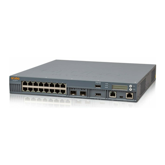
M6 x 7 mm Grounding Screws AC Power Cord Retaining Clip Power Cable USB Console Cable Rubber Feet Aruba 7010 Installation Guide (Printed) (This document) Quick Start Guide (Printed) End User License Agreement (Printed) Aruba 7010 Series Controller | Installation Guide 7010 Controller |... -
Page 8: 7010 Components
Used to select the LCD screen menu Enter Button Used to execute actions on the LCD Screen USB Interface 2 x USB 2.0, USB storage device can be used to save and upload configurations | 7010 Controller | Installation Guide Aruba 7010 Series Controller... -
Page 9: Access Ports (Ethernet Ports)
STATUS: Placed on the right side of the port, and displays the status of the port based on the information displayed by this LED changes based on LCD’s mode. | Installation Guide 7010 Controller | Aruba 7010 Series Controller... -
Page 10: Uplink Ports
The Aruba 7010 controller includes two 1000BASE-X uplink ports (16 and 17). See Figure 4. It is recommended to use Aruba supported SFP transceivers in these ports. Figure 4 Ports, LEDs, and LCD Panel | 7010 Controller | Installation Guide Aruba 7010 Series Controller... -
Page 11: Power, Status, And Peered Leds
Power On Power Off Status System status Green (Solid) Operational Green (Blinking) Device is loading software Amber (Blinking) Major alarm Amber (Solid) Critical alarm No power Peered Reserved for future use | Installation Guide 7010 Controller | Aruba 7010 Series Controller... -
Page 12: Lcd Panel
Completes the reading or writing of the attached USB device. Reload system [Y|N] Allows you to reboot the device. Halt system [Y|N] Allows you to halt the device. Exit Exits Maintenance menu. | 7010 Controller | Installation Guide Aruba 7010 Series Controller... -
Page 13: Usb Interface
LEDs provide status information as shown in the following table: Table 9 10/100/1000BASE-T (RJ-45) Management Port Function Indicator Status LINK/ACT Link Status Information Green (Solid) Link has been established Green (Blinking) Link activity No link on port | Installation Guide 7010 Controller | Aruba 7010 Series Controller... -
Page 14: Mini Usb Console Connector
Baud Rate Data Bits Parity Stop Bits Flow Control 9600 None None The CONSOLE port is compatible only with RS-232 devices. Non-RS-232 devices, such as APs, are not supported. CAUTION | 7010 Controller | Installation Guide Aruba 7010 Series Controller... -
Page 15: Power Supply
Aruba does not guarantee proper functionality of non-approved third party optics when used in an Aruba system. For a complete list of Aruba approved optics, contact your Aruba sales representative. | Installation Guide 7010 Controller | Aruba 7010 Series Controller... - Page 16 Aruba SFP, 1000BASE-LX, LC Connector; 310nm pluggable GbE optic; up to 10,000 meters over single-mode fiber. SFP-TX Aruba SFP, 1000BASE-T SFP; copper GbE pluggable; RJ45 connector; up to 100 meters over Category- 5, 5e, 6 and 6a unshielded twisted pair cable. | 7010 Controller | Installation Guide Aruba 7010 Series Controller...
-
Page 17: Installation
Do not allow the controller’s chassis, network ports, power supply, or mounting brackets to contact any device, cable, object, or person attached to a different electrical ground. Also, never connect the device to external storm grounding sources. Aruba 7010 Series Controller | Installation Guide Installation |... -
Page 18: Selecting A Location
Suitable Screwdrivers for all screw types provided in the box (not included in the kit) Some racks require screws that differ from those included with the 7010 controller. Ensure that you have the correct screws before installing the 7010 controller. | Installation | Installation Guide Aruba 7010 Series Controller... -
Page 19: Installation Steps
Leave a minimum of 10 cm (4 inches) of space on the left and right side of the controller for proper air flow and ventilation. Leave additional space in the front and the back of the controller to access network cables, LED status indicators, and power cord. | Installation Guide Installation | Aruba 7010 Series Controller... -
Page 20: Required Tools And Equipment
Suitable Screwdrivers for all screw types (not included in the kit) Installation Steps To install a 7010 controller on a wall: Ensure that the Ethernet ports are facing down when installing the 7010 controller on a wall. | Installation | Installation Guide Aruba 7010 Series Controller... - Page 21 3. Create the holes and insert wall anchors if your installation requires them. 4. Align the mounting bracket holes with the holes you created in the wall (see Figure 11). 5. Use appropriate screws to secure the 7010 controller. | Installation Guide Installation | Aruba 7010 Series Controller...
-
Page 22: Connecting And Disconnecting The Ac Power Cord
To disconnect the AC power cord from the 7010 controller: 1. Lift the power cord retaining clip off the AC power cord. 2. Pull the AC power cord from the power supply module. | Installation | Installation Guide Aruba 7010 Series Controller... -
Page 23: Installing An Sfp
To disconnect an LC fiber optic cable from an SFP-SX or SFP-LX module: 1. Depress the transceiver handle to release the latch on the cable and simultaneously pull the cable out of the port. | Installation Guide Installation | Aruba 7010 Series Controller... - Page 24 Figure 13 Connecting an LC Fiber Optic Cable | Installation | Installation Guide Aruba 7010 Series Controller...
-
Page 25: Specifications, Safety, And Compliance
Industry Canada This Class A digital apparatus complies with Canadian ICES-003.” & “Cet appareil numérique de la classe A est conforme à la norme NMB-003 du Canada. Aruba 7010 Series Controller | Installation Guide Specifications, Safety, and Compliance |... - Page 26 California and other certain states. See www.dtsc.ca.gov/hazardouswaste/perchlorate for more information. CAUTION Risk of explosion if battery is replaced by an incorrect type. Dispose of used batteries according to the instructions. WARNING Japan VCCI | Specifications, Safety, and Compliance | Installation Guide Aruba 7010 Series Controller...
- Page 27 Rules, governed by the Ministry of Environment & Forests, Government of India. China RoHS Aruba products also comply with China environmental declaration requirements and are labeled with the “EFUP 50” label shown at the left. | Installation Guide Specifications, Safety, and Compliance | Aruba 7010 Series Controller...
- Page 28 The Environment- Friendly Use Period (EFUP) for all enclosed products and their parts are per the symbol shown here. The Environment- Friendly Use Period is valid only when the product is operated under the conditions defined in the product manual. | Specifications, Safety, and Compliance | Installation Guide Aruba 7010 Series Controller...
Need help?
Do you have a question about the Aruba 7010 Series and is the answer not in the manual?
Questions and answers