Table of Contents
Advertisement
Quick Links
KIT_T2G-B-E_LITE user guide
About this document
Scope and purpose
This document serves as a guide for using the KIT_T2G-B-E_LITE. This document explains the kit operation,
describes the Sample Driver Library (SDL) and its operation, and the hardware details of the board.
Intended audience
This document is intended for KIT_T2G-B-E_LITE users.
Reference documents
This user guide should be read in conjunction with the following documents:
AN220118 - Getting started with TRAVEO™ T2G family MCUs
•
TRAVEO™ T2G Body Entry (CYT2BL series) datasheet
•
User Guide
www.infineon.com
Please read the Important Notice and Warnings at the end of this document
002-37239 Rev. **
2023-07-20
Advertisement
Table of Contents

Subscribe to Our Youtube Channel
Related Manuals for Infineon KIT T2G-B-E LITE


Summary of Contents for Infineon KIT T2G-B-E LITE
-
Page 1: About This Document
This user guide should be read in conjunction with the following documents: AN220118 - Getting started with TRAVEO™ T2G family MCUs • TRAVEO™ T2G Body Entry (CYT2BL series) datasheet • User Guide Please read the Important Notice and Warnings at the end of this document 002-37239 Rev. ** www.infineon.com 2023-07-20... -
Page 2: Table Of Contents
KIT_T2G-B-E_LITE user guide Table of contents Table of contents About this document ........................1 Table of contents ..........................2 Safety and regulatory compliance information .................. 3 General safety instructions ......................3 Introduction .......................... 4 Getting started............................4 Additional learning resources ......................... 4 Technical support............................ -
Page 3: Safety And Regulatory Compliance Information
General safety instructions ESD protection ESD can damage boards and associated components. Infineon recommends that you perform procedures only at an ESD workstation. If an ESD workstation is unavailable, use appropriate ESD protection by wearing an anti- static wrist strap attached to the chassis ground (any unpainted metal surface) on your board when handling parts. -
Page 4: Introduction
SDL is provided as an executable, tested on Windows 10 with a minimum installation size requirement of • around 400 MB. Additional learning resources Infineon provides a wealth of data at www.infineon.com/cms/en/product/microcontroller/32-bit-traveo- t2g-arm-cortex-microcontroller to help you to select the right TRAVEO™ T2G MCU device for your design and to help you quickly and effectively integrate the device into your design. -
Page 5: Technical Support
KIT_T2G-B-E_LITE user guide Introduction Technical support For assistance, go to www.infineon.com/support. Visit community.infineon.com to ask your questions in Infineon developer community. You can also use the following support resources if you need quick assistance: Self-help (Technical documents) • Documentation conventions... - Page 6 KIT_T2G-B-E_LITE user guide Introduction Abbreviation Definition inter-integrated circuit Inter-IC Sound light-emitting diode low power oscillator personal computer peripheral driver library QSPI Quad serial peripheral interface SDHC Secure Digital Host Controller SDIO Secure Digital Input Output software development kit SMIF Serial Memory Interface Serial Peripheral Interface SRAM static random-access memory...
-
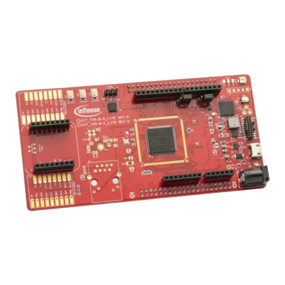
Page 7: Kit Details
Kit contents KIT_T2G-B-E_LITE board • Figure 1 Kit contents Inspect the contents of the kit; if you find any part missing, go to https://www.infineon.com/cms/en/product/microcontroller/32-bit-traveo-t2g-arm-cortex- microcontroller/32-bit-traveo-t2g-arm-cortex-for-body/traveo-t2g-cyt2bl-series. Board details The KIT_T2G-B-E_LITE has the following features: TRAVEO™ T2G-B-E MCU. See the device datasheet. •... - Page 8 KIT_T2G-B-E_LITE user guide Kit details Figure 2 KIT_T2G-B-E_LITE board – top view Shield2Go connectors (Not Mounted) (J7, J19) MikroBUS connectors (J11, J12) 32.768-kHz oscillator for WCO (Y1) 16-MHz oscillator for ECO (Y2) 8-pin Arduino header (J13) Expansion header 1 (X1) 6-pin Arduino header (J15) DC Power Jack (J1) Power LED (LED2)
- Page 9 KIT_T2G-B-E_LITE user guide Kit details USER LED1 (LED3) Expansion Header 1 (X2) 10-pin Arduino header (J16) CAN FD transceiver (U8) CAN FD connector (J5) USER2 button (SW3) USER1 button (SW2) RESET button (SW1) KIT_T2G-B-E_LITE board pinout details mikro BUS MISO MOSI GPIO GPIO...
- Page 10 KIT_T2G-B-E_LITE user guide Kit details Table 3 KIT_T2G-B-E_LITE board pinout Primary onboard function Secondary onboard Connection details function TRAVEO™ T2G-B-E MCU pins XRES Hardware reset – P12[0] CAN transmit CAN_TX – Connected to TxD of CAN FD transceiver TLE9251VSJ P12[1] CAN receive CAN_RX –...
- Page 11 KIT_T2G-B-E_LITE user guide Kit details Primary onboard function Secondary onboard Connection details function P2[0] Pin D4 of connector J14.5 compatible – – with Arduino P2[1] Pin D5 of connector J14.6 compatible – – with Arduino P14[3] Pin D6 of connector J14.7 compatible –...
- Page 12 KIT_T2G-B-E_LITE user guide Kit details Primary onboard function Secondary onboard Connection details function P23[5] SWCLK_TCLK DEBUG MIPI 10/20 – Connector (J4.4) P23[6] SWDIO_TMS DEBUG MIPI 10/20 – Connector (J4.2) P23[7] SWDOE_TDI DEBUG MIPI 10/20 – Connector (J4.8) P18[3] TRACE_CLK DEBUG MIPI 10/20 –...
-
Page 13: Kit Operation
KIT_T2G-B-E_LITE user guide Kit operation Kit operation Theory of operation The TRAVEO™ T2G-B-E evaluation board is built around TRAVEO™ T2G-B-E MCU. For details of device features, see the device datasheet. CPU Subsystem CYT2BL SWJ/MTB/CTI MXS40-HT SWJ/ETM/ITM/CTI CRYPTO eCT Flash ASIL-B SRAM0 SRAM1 Arm Cortex... - Page 14 KIT_T2G-B-E_LITE user guide Kit operation Infine on Parts Loade d Parts No L oad Par ts St atus L ED Mode Sw itch (16 MHz) WCO (32.768 KHz) 20 /10 Pin JTAG/ Reset Butt on SWD/ETM Header P5LP_VDD Potentiometer Arduino Headers KitProg3 KitProg3 USB (PSoC 5LP)
- Page 15 KIT_T2G-B-E_LITE user guide Kit operation The KIT_T2G-B-E_LITE board has the following peripherals: Table 4 Peripheral details Sl. No. Peripheral Description Shield2Go Connector Option connector for Shield2Go Interface (DNI) MikroBUS Connector Option connector for MikroBUS Interface (DNI) 32.768 kHz crystal for WCO (Y1) Oscillator for WCO clock.
- Page 16 KIT_T2G-B-E_LITE user guide Kit operation Sl. No. Peripheral Description Potentiometer (VR1) 10-kΩ potentiometer connected to TRAVEO™ T2G-B-E MCU pin P6[0]. It can be used to simulate a sensor output to TRAVEO™ T2G-B-E MCU. User LEDs (LED5) The user LEDs can operate at the entire operating voltage range of the TRAVEO™...
-
Page 17: Kitprog3: Onboard Programmer/Debugger
KIT_T2G-B-E_LITE user guide Kit operation KitProg3: Onboard programmer/debugger The TRAVEO™ T2G-B-E evaluation board can be programmed and debugged using the onboard KitProg3. KitProg3 is an onboard programmer/debugger with USB-UART, USB-I2C, and USB-SPI Bridge (not supported on this board) functionality. KitProg3 supports CMSIS-DAP only and does not support mass storage. A PSoC™ 5LP device is used to implement the KitProg3 functionality. - Page 18 KIT_T2G-B-E_LITE user guide Kit operation Figure 8 Open Sample Driver Library Select Make icon and execute. If compiling succeeds, then select download and debug and execute. Confirm the debug execution. Figure 9 Open Sample Driver Library using IAR EWARM User Guide 002-37239 Rev.
-
Page 19: Usb-Uart Bridge
KIT_T2G-B-E_LITE user guide Kit operation 3.2.2 USB-UART bridge KitProg3 on the TRAVEO™ T2G-B-E evaluation board can act as a USB-UART bridge. The UART Rx and Tx pins of KitProg3 are connected to the TRAVEO™ T2G-B-E MCU UART pins as follows: KitProg3 TRAVEO T2G-B-E MCU... -
Page 20: Hardware
KIT_T2G-B-E_LITE user guide Hardware Hardware KIT_T2G-B-E_Lite kit connections 4.1.1 USER LEDs The correspondence between the LEDs on the board and the CYT2BL5xx device pins and the port pins are shown in Table Table 5 USER LEDs CYT2BL5xx USER LED Part number USER LED 1 LED3 P5.0... -
Page 21: System Configuration
KIT_T2G-B-E_LITE user guide Hardware Table 8 MODE switch PSoC 5LP USER switch Part Number MODE SW P1[2] System configuration Install the KitProg3 USB-UART driver to work with starter kit KitProg3 User Guide . For software and tool TRAVEO T2G Body Entry Lite Kit - Getting Started configuration, see Schematics This section shows the schematics of the TRAVEO T2G Body Entry Lite Kit. - Page 22 KIT_T2G-B-E_LITE user guide General safety instructions Figure 12 Power supply - 1 User Guide 002-37239 Rev. ** 2023-07-20...
- Page 23 KIT_T2G-B-E_LITE user guide General safety instructions Figure 13 Power supply - 2 User Guide 002-37239 Rev. ** 2023-07-20...
- Page 24 KIT_T2G-B-E_LITE user guide General safety instructions Figure 14 KitProg3 Interface User Guide 002-37239 Rev. ** 2023-07-20...
- Page 25 KIT_T2G-B-E_LITE user guide General safety instructions Figure 15 TRAVEO™ T2G MCU Power User Guide 002-37239 Rev. ** 2023-07-20...
- Page 26 KIT_T2G-B-E_LITE user guide General safety instructions Figure 16 TRAVEO™ T2G-B-H-8M 176-pin MCU - 1 User Guide 002-37239 Rev. ** 2023-07-20...
- Page 27 KIT_T2G-B-E_LITE user guide General safety instructions Figure 17 TRAVEO™ T2G-B-H-8M 176-pin MCU - 2 User Guide 002-37239 Rev. ** 2023-07-20...
- Page 28 KIT_T2G-B-E_LITE user guide General safety instructions Figure 18 TRAVEO™ T2G-B-H-8M 176-pin MCU - 3 User Guide 002-37239 Rev. ** 2023-07-20...
- Page 29 KIT_T2G-B-E_LITE user guide General safety instructions Figure 19 TRAVEO™ T2G-B-H-8M 176-pin MCU - 4 User Guide 002-37239 Rev. ** 2023-07-20...
- Page 30 KIT_T2G-B-E_LITE user guide General safety instructions Figure 20 TRAVEO™ T2G-B-H-8M 176-pin MCU - 5 User Guide 002-37239 Rev. ** 2023-07-20...
- Page 31 KIT_T2G-B-E_LITE user guide General safety instructions Figure 21 TRAVEO™ T2G-B-E-1M 100-pin MCU User Guide 002-37239 Rev. ** 2023-07-20...
- Page 32 KIT_T2G-B-E_LITE user guide General safety instructions Figure 22 Peripheral interface User Guide 002-37239 Rev. ** 2023-07-20...
- Page 33 KIT_T2G-B-E_LITE user guide General safety instructions Figure 23 CAN and QSPI interface User Guide 002-37239 Rev. ** 2023-07-20...
- Page 34 KIT_T2G-B-E_LITE user guide General safety instructions Figure 24 Ethernet interface User Guide 002-37239 Rev. ** 2023-07-20...
- Page 35 KIT_T2G-B-E_LITE user guide General safety instructions Figure 25 Shield2Go / MikroBUS User Guide 002-37239 Rev. ** 2023-07-20...
- Page 36 KIT_T2G-B-E_LITE user guide General safety instructions User Guide 002-37239 Rev. ** 2023-07-20...
- Page 37 KIT_T2G-B-E_LITE user guide Figure 26 Arduino Headers General safety instructions Figure 27 Expansion headers User Guide 002-37239 Rev. ** 2023-07-20...
-
Page 38: Layouts
KIT_T2G-B-E_LITE user guide General safety instructions Layouts This section shows the board layouts of the TRAVEO T2G Body Entry Lite Kit. User Guide 002-37239 Rev. ** 2023-07-20... - Page 39 KIT_T2G-B-E_LITE user guide General safety instructions Figure 28 Top view User Guide 002-37239 Rev. ** 2023-07-20...
- Page 40 KIT_T2G-B-E_LITE user guide General safety instructions Figure 29 Bottom view User Guide 002-37239 Rev. ** 2023-07-20...
-
Page 41: Revision History
KIT_T2G-B-E_LITE user guide Revision history Revision history Document Date Description revision 2023-07-20 Initial release User Guide 002-37239 Rev. ** 2023-07-20... - Page 42 Technologies hereby disclaims any and all authorized representatives of Infineon Technologies, warranties and liabilities of any kind, including Infineon Technologies’ products may not be used in without limitation warranties of non-infringement any applications where a failure of the product or any ©...
Need help?
Do you have a question about the KIT T2G-B-E LITE and is the answer not in the manual?
Questions and answers