Table of Contents
Advertisement
Quick Links
C 3610DRJ (X)
Model
Cordless Table Saw
SAFETY INSTRUCTIONS AND INSTRUCTION MANUAL
WARNING
IMPROPER OR UNSAFE use of this power tool can result in death or serious bodily injury!
This manual contains important information about product safety. Please read and understand this manual
BEFORE operating the power tool. Please keep this manual available for other users and owners before
they use the power tool. This manual should be stored in safe place.
Advertisement
Table of Contents

Related Manuals for HIKOKI C 3610DRJX


Summary of Contents for HIKOKI C 3610DRJX
- Page 1 C 3610DRJ (X) Model Cordless Table Saw SAFETY INSTRUCTIONS AND INSTRUCTION MANUAL WARNING IMPROPER OR UNSAFE use of this power tool can result in death or serious bodily injury! This manual contains important information about product safety. Please read and understand this manual BEFORE operating the power tool.
-
Page 2: Table Of Contents
CONTENTS SECTION PAGE SYMBOLS ................................3 SAFETY INSTRUCTIONS ...........................4 OVERVIEW ...............................10 SPECIFICATIONS..............................11 LOOSE PARTS ..............................12 ASSEMBLY ...............................13 OPERATION ..............................22 ADJUSTMENTS ..............................30 MAINTENANCE ..............................32 TROUBLESHOOING ............................33 SELECTING ACCESSORIES ...........................34 GUARANTEE ..............................34... -
Page 3: Symbols
English SYMBOLS The following show symbols used for the machine. Be sure that you understand their meaning before use. Symbol Meaning C 3610DRJ (X): Cordless table saw To reduce the risk of injury, user must read instruction manual. Always wear eye protection. Always wear hearing protection. -
Page 4: Safety Instructions
English SAFETY INSTRUCTIONS General power tool safety warnings WARNING: Read all safety warnings, instructions, illustrations and specifications provided with this power tool. Failure to follow all instructions listed below may result in electric shock, fire and/or serious injury. Save all warnings and instructions for future reference. The term “power tool”... - Page 5 English c) When battery pack is not in use, keep it away from other metal objects, like paper clips, coins, keys, nails, screws or other small metal objects, that can make a connection from one terminal to another. Shorting the battery terminals together may cause burns or a fire.
- Page 6 • If this saw makes an unfamiliar noise or if it vibrates excessively, cease operating immediately, turn unit off and remove the battery pack until the problem has been located and corrected. Contact a HiKOKI Authorized Service Center if the problem can not be found.
- Page 7 English when using this product, even if you turn the switch on, the motor may stop. This is not the trouble but the result of protection function. 1. When the battery power remaining runs out, the motor stops. In such case, charge it up immediately. 2.
- Page 8 English NOTE: • There may be an occasional pause during USB recharging. • When a USB device is not being charged, remove the USB device from the charger. Failure to do so may not only reduce the battery life of a USB device, but may also result in unexpected accidents. •...
- Page 9 English GLOSSARY OF TERMS The safe use of this product requires an understanding of the information on the tool and in this operator’s manual as well as a knowledge of the project you are attempting. Before use of this product, familiarize yourself with all operating features and safety rules. •...
-
Page 10: Overview
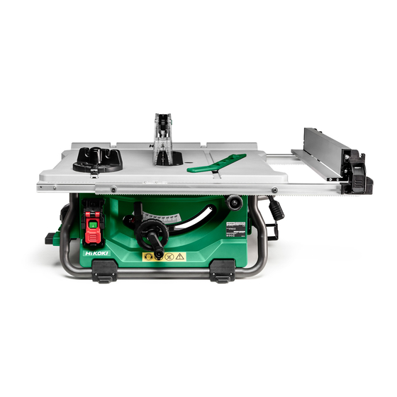
English OVERVIEW Anti-kickback pawls Height adjusting knob Blade wrench Dust extraction port Riving knife Bevel lock lever Working table Small baffle Narrow fence Bevel indicator Outfeed support Anti-kickback pawls storage Rip fence Switch assembly Blade guard Blade guard storage Rip fence lock lever Mitre gauge lock knob Saw blade Handle II... -
Page 11: Specifications
English SPECIFICATIONS Cordless Table Saw Input Voltage 36 V DC Ambient Operating Temperature Range -10°C ~ 40°C No Load Speed 5000/min Blade Size ø254mm × ø30mm × 2.4mm, 40T Bevel Range 0°~45° Working Table Size 730mm x 559mm Outfeed Support Size 730mm x 50mm Max. -
Page 12: Loose Parts
English LOOSE PARTS The following items are included with your table saw: PART DESCRIPTION QUANTITY Table saw assembly Mitre gauge (in stored position) Blade guard assembly (in stored position) Anti-kickback pawls assembly (in stored position) Outfeed support assembly Rip fence assembly (in stored position) Push stick (in stored position) Blade wrench 4mm Hex key... -
Page 13: Assembly
English ASSEMBLY UNPACKING YOUR TABLE SAW This product requires assembly. ◌ Carefully lift saw from the carton and place it on a level work surface. ◌ Inspect the tool carefully to make sure that no breakage or damage occurred during shipping. ◌... - Page 14 English TO REMOVE/REPLACE/ALIGN THE TABLE INSERT (Fig. 2a-2b) WARINING: The table insert must be level with the saw table. If the table insert is too high or too low, the workpiece can catch on the uneven edges, resulting in binding or kickback, which could result in serious personal injury.
- Page 15 English REMOVING AND INSTALLING THE BLADE (Fig. 4a-4b) CAUTION: Check the arbor hole diameter of the blade before installing the blade. Always use the correct ring for the arbor hole of the blade you intend to use. CAUTION: To work properly, the saw blade teeth must point down toward the front of the saw. Failure to heed this instruction could cause damage to the saw blade, the saw or the workpiece.
- Page 16 English ◌ Pull out and hold knob (47). Align slot in anti-kickback pawls (1) over the slot A (48) indicated of riving knife (2). Place the spring pin (49) on the anti-kickback pawls (1) into the slot (A) (48) indicated on the riving knife (2). ◌...
- Page 17 English OUTFEED SUPPORT ASSEMBLY INSTALLATION (Fig. 7a-7b) ◌ Loosen and remove two stop screws (58) on the extension poles (59) of the outfeed support (22). ◌ Loosen the locking knobs (60) under the working table counterclockwise. ◌ Insert the extension poles (59) into the two holes in the rear of the working table and into the extension tube brackets that are located under the working table.
- Page 18 English Fig. 8c MITRE GAUGE INSTALLATION (Fig. 9a-9b) The mitre gauge (18) can be installed on each mitre gauge groove (37) on either side of blade. ◌ Remove the mitre gauge (18) from mitre gauge storage (27) located on inside of the right side of saw. ◌...
- Page 19 English Fig. 10c Fig. 10d CONNECT TO A DUST COLLECTION SYSTEM (Fig. 11) The dust extraction port (29) with 63.5 mm size is located on the back of the table saw. This port can be connected directly to a dust collection system by connecting the pick up end of the dust collection hose to the dust port.
- Page 20 English CHARGING (Fig. 13) Battery and battery charger are not included with this product. Before using the power tool, charge the battery as follows. ◌ Connect the charger’s power cord to the receptacle. When connecting the plug of the charger to a receptacle, the charge indicator lamp will blink in red (At 1- second intervals).
- Page 21 English Regarding electric discharge in case of new batteries, etc. As the internal chemical substance of new batteries and batteries that have not been used for an extended period is not activated, the electric discharge might be low when using them the first and second time. This is a temporary phenomenon, and normal time required for recharging will be restored by recharging the batteries 2 –...
-
Page 22: Operation
WARINING: If this saw makes an unfamiliar noise or if it vibrates excessively, cease operating immediately, turn unit off and remove the battery pack until the problem has been located and corrected. Contact a HiKOKI factory service center or a HiKOKI authorized service center if the problem cannot be found. - Page 23 English ◌ Using the wrong blade for the type of cut. ◌ Not following correct operating procedures. ◌ Misusing the saw. ◌ Failing to use the anti-kickback pawls. ◌ Cutting with a dull, gummed-up, or improperly set blade. PRECAUTIONS OF KICKBACK NOTE: Kickback can be avoided by taking following proper precautions: •...
- Page 24 English CHANGING BLADE ANGLE (BEVEL) (Fig. 18) CAUTION: A 90° cut has a 0° bevel and a 45° cut has a 45° bevel. CAUTION: If bevel indicator is not at zero when saw blade is at 0°, see the section “Adjusting bevel indicator” (Page 31). ◌...
- Page 25 English MITRE GAUGE (Fig. 20) The mitre gauge (18) provides accuracy in angled cuts. For very close tolerances, test cut are recommended. There are two mitre gauge grooves, one on either side of blade. When making a 90° cross cut, use either mitre gauge groove. When making a beveled cross cut (blade tilted in relation to working table, mitre gauge should be located in groove on right so that blade is tilted away from mitre gauge and hands.
- Page 26 English CUTTING TIPS ◌ The kerf (the cut made by the blade in the wood) will be wider than the blade to avoid overheating or binding. Make allowance for the kerf when measuring wood. ◌ Make sure the kerf is made on the waste side of the measuring line. ◌...
- Page 27 English MAKING A MITRE CUT (Fig. 26) ◌ Remove rip fence. ◌ Set blade to correct depth for workpiece. ◌ Set mitre gauge (18) to the desired angle and tighten lock knob (15). ◌ Make sure the wood is clear of the blade before turning on the saw. ◌...
- Page 28 English MAKING A COMPOUND (BEVEL) MITRE CUT (Fig. 29) ◌ Remove rip fence. ◌ Unlock bevel lock lever. ◌ Adjust bevel angle to desired setting. ◌ Lock bevel lock lever. ◌ Set blade to correct depth for workpiece. ◌ Set mitre gauge (18) to desired angle and tighten lock knob (15). ◌...
- Page 29 English DUST COLLECTION (Fig. 31) This table saw is equipped with a dustshroud and dust collection port. For best results, connect a vacuum to the port at the rear of the saw. After extended use, the saw’s dust collection system may become clogged. To clear the dust collection system: ◌...
-
Page 30: Adjustments
English ADJUSTMENTS WARNING: Before performing any adjustment, remove the battery pack and turn the switch off. Failure to do so could result in serious personal injury. WARNING: Make sure the blade guard is reinstalled immediately after making any adjustment which requires it to be removed. Failure to heed this instruction could result in serious personal injury. - Page 31 English ◌ Remove the anti-kickback pawls and blade guard. ◌ Using a triangle square (78), set the blade (24) to exactly 45°. ◌ If the blade stops bevelling before it gets to 45°, loosen the 45° stop set screw (79) (located at the right of the bevel track on the front), and then adjust it to 45°. ◌...
-
Page 32: Maintenance
All quality power tools will eventually require servicing or replacement of parts because of wear from normal use. To assure that only authorized replacement parts will be used, all service (other than routine maintenance) must be performed by an HiKOKI Authorized Service Center ONLY. -
Page 33: Troubleshooing
WARNING: To avoid injury from an accidental start, turn the switch OFF and remove the battery from the main body before making any adjustments. All electrical or mechanical repairs should be done only by qualified service technicians. Contact HiKOKI Authorized Service Center. -
Page 34: Selecting Accessories
The accessories of this machine are listed on page 12 (Refer to “LOOSE PARTS” and “OPTIONAL ACCESSORIES” chapter ). CAUTION: Repair, modification and inspection of HiKOKI Power Tools must be carried out by a HiKOKI Authorized Service Center. In the operation and maintenance of power tools, the safety regulations and standards prescribed in Australia must be observed. - Page 35 Hikoki Power Tools Australia Pty. Ltd. Unit 1, 10 Boden Road, Seven Hills, NSW 2147, Australia Code No. C99739711 Printed in China...
Need help?
Do you have a question about the C 3610DRJX and is the answer not in the manual?
Questions and answers