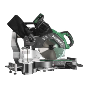
HIKOKI C 3612DRA Handling Instructions Manual
Cordless slide compound miter saw
Hide thumbs
Also See for C 3612DRA:
- Handling instructions manual (420 pages) ,
- Handling instructions manual (32 pages)

Related Manuals for HIKOKI C 3612DRA


Summary of Contents for HIKOKI C 3612DRA
- Page 1 充电式滑动复合式斜口锯 Cordless Slide Compound Miter Saw C 3612DRA 保留备用 Keep for future reference 使用说明书 Handling instructions...
-
Page 2: Table Of Contents
中文 目次 电动工具通用安全警告........................2 斜口锯的安全说明..........................5 使用滑动复合式斜口锯的注意事项.................... 7 锂离子电池使用注意事项........................ 9 锂离子电池运输............................ 11 USB设备连接器使用注意事项(UC18YSL3)(另售)..............12 符号................................12 零件名称..............................13 规格................................14 标准附件..............................16 用途................................17 电池的拆卸/安装法.......................... 17 充电................................18 作业之前..............................21 切割之前..............................26 实际应用..............................32 安装和拆卸锯条............................ 44 LED 灯警示信号............................ 46 剩余电池电量指示灯.......................... 47 主体的运输.............................. - Page 3 中文 混乱和黑暗的场地会引发事故。 b) 不要在易爆环境,如有易燃液体、气体或粉尘的环境下操作电动工 具。 电动工具产生的火花会点燃粉尘或气体。 让儿童和旁观者离开后操作电动工具。 注意力不集中会使操作者失去对工具的控制。 电气安全 a) 电动工具插头必须与插座相配。绝不能以任何方式改装插头。需接地 的电动工具不能使用任何转换插头。 未经改装的插头和相配的插座将减少电击危险。 b) 避免人体接触接地表面,如管道、散热片和冰箱。 如果你身体接地会增加电击危险。 不得将电动工具暴露在雨中或潮湿环境中。 水进入电动工具将增加电击危险。 d) 不得滥用电线。绝不能用电线搬运、拉动电动工具或拔出其插头。使 电线远离热源、油、锐边或运动部件。 受损或缠绕的软线会增加电击危险。 当在户外使用电动工具时,使用适合户外使用的外接软线。 适合户外使用的软线将减少电击危险。 如果在潮湿环境下操作电动工具是不可避免的,应使用剩余电流动作 保护器(RCD)。 使用RCD可减小电击危险。 人身安全 a) 保持警觉,当操作电动工具时关注所从事的操作并保持清醒。当你感 到疲倦,或在有药物、酒精或治疗反应时,不要操作电动工具。 在操作电动工具时瞬间的疏忽会导致严重人身伤害。 b) 使用个人防护装置。始终佩戴护目镜。 安全装置,诸如适当条件下使用防尘面具、防滑安全鞋、安全帽、听 力防护等装置能减少人身伤害。 防止意外起动。确保开关在连接电源和/或电池盒、拿起或搬运工具 时处于关断位置。 手指放在已接通电源的开关上或开关处于接通时插入插头可能会导致 危险。 d) 在电动工具接通之前,拿掉所有调节钥匙或扳手。...
- Page 4 中文 宽松衣服、佩饰或长发可能会卷入运动部件中。 g) 如果提供了与排屑、集尘设备连接用的装置,要确保它们连接完好且 使用得当。 使用这些装置可减少尘屑引起的危险。 h) 请勿因频繁使用工具的熟悉感而掉以轻心,忽视工具的安全性原则。 粗心的行为可能会导致瞬间发生严重伤害。 电动工具使用和注意事项 a) 不要滥用电动工具,根据用途使用适当的电动工具。 选用适当设计的电动工具会使你工作更有效、更安全。 b) 如果开关不能接通或关断工具电源,则不能使用该电动工具。 不能用开关来控制的电动工具是危险的且必须进行修理。 在进行任何调整、更换附件或存放电动工具之前,必须从电源上拔掉 插头和/或取下电池盒(如果可拆卸)。 这种防护性措施将减少工具意外起动的危险。 d) 将闲置不用的电动工具贮存在儿童所及范围之外,并且不要让不熟悉 电动工具或对这些说明不了解的人操作电动工具。 电动工具在未经培训的用户手中是危险的。 维护电动工具和附件。检查运动件是否调整到位或卡住,检查零件破 损情况和影响电动工具运行的其他状况。如有损坏,电动工具应在使 用前修理好。 许多事故由维护不良的电动工具引发。 保持切削刀具锋利和清洁。 保养良好的有锋利切削刃的刀具不易卡住而且容易控制。 g) 按照使用说明书,考虑作业条件和进行的作业来使用电动工具、附件 和工具的刀头等。 将电动工具用于那些与其用途不符的操作可能会导致危险。 h) 保持手柄和抓握表面干燥、清洁,远离油和油脂。 如果手柄和抓握表面湿滑,可能导致在发生意外情况时,无法安全操 作和控制工具。 电池式工具使用和注意事项 a) 只用制造商规定的充电器充电。 将适用于某种电池盒的充电器用到其他电池盒时会发生着火危险。...
-
Page 5: 斜口锯的安全说明
中文 从电池中溅出的液体会发生腐蚀或燃烧。 请勿使用损坏或改装的电池盒或工具。 损坏或改装的电池可能会引发突发状况,导致火灾、爆炸或受伤。 请勿将电池盒或工具暴露在有火源或高温环境中。 如果暴露在有火源或130度以上高温的环境中,可能引起爆炸。 g) 请完全按照充电说明进行操作,不要在说明中规定的温度范围外的环 境中对电池盒或工具充电。 充电不当或在规定温度范围外的环境中充电可能会导致电池损坏,增 加发生火灾的风险。 维修 a) 将你的电动工具送交专业维修人员,使用同样的备件进行修理。 这样将确保所维修的电动工具的安全性。 b) 请勿维修已损坏的电池盒。 需由制造商或经授权的服务供应商进行维修。 注意! 不可让儿童和体弱人士靠近工作场所。 应将不使用的工具存放在儿童和体弱人士接触不到的地方。 斜口锯的安全说明 斜口锯用于切割木材或木材类似品,请勿与切割砂轮搭配用以切割铁质材 料,如杆件、棒材、螺柱等。 磨屑会导致下护罩等移动部件卡住。磨削切割会产生火花,烧毁下护罩、 切口插入件和其他塑料部件。 尽可能使用夹扣来支撑工件。如果用手支撑工件,须始终保持手与锯片两 侧相距至少100mm。请勿使用本锯来切割无法牢固夹紧或手持的过小工 件。 如果手与锯片靠得太近,会增加与锯片接触而受伤的风险。 工件务必保持不动,夹紧或抵在挡板和工作台上。不得以任何“徒手”的 方式将工件送入锯片中或进行切割。 未固定或移动的工件可能会被高速抛出,导致受伤。 将斜口锯推过工件。请勿将斜口锯拉过工件。如要切割,请在不切割的状 态下抬起锯头并拉出至工件上方,启动电机,按下锯头并将斜口锯推过工 件。 在回拉行程中进行切割时,很可能导致锯片爬升到工件顶部并将锯片组件 猛地抛向操作者。 无论在锯片的前方还是后方位置,切不可将手横过预定切割线。... - Page 6 中文 以“交叉手”方式支撑工件(即,用左手将工件靠于锯片右侧)非常危 险,反之亦然。 当锯片仍在旋转时,请勿将任何一只手伸到距离锯片两侧100mm以内的挡 板后方清理木屑或出于任何其他原因进行操作。 旋转中的锯片与手的接触距离可能不明显,因此可能会造成人员严重受 伤。 切割前,请检查工件。如果工件弯曲或卷翘,将其夹紧,使外侧弯曲面朝 向挡板。务必确保工件、挡板和工作台之间沿着切割线的部分无间隙。 弯曲或卷翘的工件可能扭曲或移位,并可能在切割时导致瓷砖锯的旋转锯 片上出现粘连。工件内不得有铁钉或异物。 工作台上除了工件外,不得有任何其他工具、木屑等,否则请勿使用本 锯。 接触旋转刀片的小切屑或松散的木片或其他物体可能会被高速抛出。 一次仅切割一个工件。 叠放的多个工件无法充分夹紧或抵牢,可能会在切割过程中粘在刀片上或 发生移位。 10. 使用前,确保斜口锯安装或放置在平坦稳固的工作表面上。 平坦稳固的工作表面会降低斜口锯变得不稳定的风险。 11. 筹划工作。每次更改斜角或斜接角度设定时,请确保用于支撑工件的可调 挡板固定稳妥,且不会干扰刀片或防护系统。 在未打开工具且工作台上无工件的情况下,请移动锯片进行完整的模拟切 割,以确保切割挡板时不存在干扰或危险。 12. 为宽于或长于台面的工件提供足够的支撑,如工作台延伸部分、锯木架 等。 如果支撑不稳,宽于或长于斜口锯工作台的工件可能会倾斜。如果切割件 或工件倾斜,其可能会支起下护罩或被旋转刀片抛出。 13. 不可由他人来充当工作台延伸部分的替代物或作为额外的支撑物使用。 工件如未作稳定支撑,会导致切割操作过程中发生刀片粘连或工件移位, 将您和协作者拉入旋转的刀片中。 14. 切割件不得以任何方式卡住或压在旋转的锯片上。 如进行限制(即,使用长度挡块),切割件可能会楔住刀片并猛地抛出。 15. 始终使用夹扣或固定装置来正确支撑杆或管之类的圆形材料。 在切割时,杆易于滚动,导致刀片“咬住”进行作业的手并将其拉入刀片 内。...
-
Page 7: 使用滑动复合式斜口锯的注意事项
19. 当进行不完全切割或在锯头完全处于下方位置之前松开开关时,请握紧手 柄。 斜口锯的制动动作可能会导致锯头突然被下拉,从而导致受伤的风险。 使用滑动复合式斜口锯的注意事项 机器周围的地面应保持水平。维护良好且无松散的物料,如碎屑与切片。 保证充足的总体或局部照明。 请勿将本电动工具用于使用说明书中所规定之外的其他用途。 维修仅能由有资格的维修人员进行。制造厂商对因非专业维修人员进行维 修及使用不当而造成的损坏和损伤概不负责。 为了保证设计的完整性,电动工具的盖罩和螺钉类不可随便拆除。 除非电线插头已从电源插座拆下,绝不可接触转动部分或附件。 应以低于铭牌上的额定输入功率进行作业。否则电动机将过载而影响工作 精度,并降低效率。 请勿使用溶剂擦拭塑料部件。因为∶汽油、冲淡剂、轻质汽油、四氯化 碳、酒精等都会使塑料损伤或发生龟裂,所以应避免使用。请勿使用上述 溶剂进行擦拭。擦拭塑料制品,可以使用稍微沾湿了肥皂水的柔布。 只能使用HiKOKI指定的更换零件。 10. 本电动工具只在更换炭刷时才可拆解。 11. 切勿切割铁金属或砖瓦材料。 12. 提供充足的总体或局部照明。原料与成品工件应位于操作员的正常工作位 置附近。 13. 必要时应使用适当的个人保护设备,可包括:听力保护,以减少听力受损 的风险。 眼部保护,以减少眼睛受伤的风险。 呼吸保护,以减少吸入有害灰尘的风险。 手套,用于操作锯条(移动锯条时应尽可能把锯条放在支架中)以及粗糙 材料。 14. 操作员应接受机器使用、调节与操作方面的充分培训。 15. 在机器运行且锯头未处于停止位置时,不得从切割区域移去工件的任何切 片或其他部分。 16. 请勿在锯片转向前面或转向侧面的状态下使用滑动复合式斜口锯。 17. 确保下护罩能够平滑地移动。... - Page 8 中文 21. 不要使用以高速钢材制造的锯条。 22. 请仅使用HiKOKI公司所推荐的锯条。 23. 锯条的外径应在305mm。 24. 须根据要切割的材料来选择锯条。 25. 请勿在锯片朝上或朝侧面的情况下操作滑动复合式斜口锯。 26. 确保工件上无任何异物(如铁钉等)。 27. 导板磨损时请予更换。 28. 请勿使用锯条切割铝材、木材或类似材料以外的材料。 29. 请仅使用制造商所推荐的复合锯切割材料。 30. 锯片更换步骤,包括重新放置的方法以及务必正确进行此步骤的警告。 31. 在切割木头时,将滑动复合式斜口锯与集尘装置相连接。 32. 开槽时要小心。 33. 搬运此电动工具时,请勿抓住其支架。应抓住手柄而不要抓住支架。 34. 须在电动机达到最大转速时才开始切割。 35. 发现异常情况时应迅速断开开关。 36. 在切断电源并等到锯条停止之后,方可对工具进行维修或调整。 37. 在进行斜接切割或斜角切割中,在锯条完全停止转动之后,方能升高锯 条。 38. 进行切割作业时,操作员必须将锯条朝外推。 39. 请充分考虑切割操作中所有可能涉及的剩余风险,如意外接触到机器上滑...
-
Page 9: 锂离子电池使用注意事项
中文 44. 操作时请确保牢牢握住工具。否则可能导致事故或受伤。(图1) 图1 锂离子电池使用注意事项 为延长使用期限,锂离子电池配备停止输出的保护功能。 若是在使用本产品时发生下列 1至3 的情况,即使按下开关,马达也可能停 止。这并非故障,而是启动保护功能的结果。 在残留的电池电力即将耗尽时,马达会停止。 在这种情况下,请立即予以充电。 若工具超过负荷,马达亦可能停止。在这种情况下,请松开工具的开关, 试着消除超过负荷的原因。之后您就可以再度使用。 若电池在过载工作情况下过热,电池电力可能会中止。 在这种情况下,请停止使用电池,让电池冷却。之后您就可以再度使用。 此外,请留心下列的警告及注意事项。 警告! 为防止发生电池漏电、发热、冒烟、爆炸及提前点燃,请确保留意下列事项。 确保电池上没有堆积削屑及灰尘。 ○ 在工作时确定削屑及灰尘没有掉落在电池上。 ○ 确定所有工作时掉落在电动工具上的削屑和灰尘没有堆积在电池上。 ○ 请勿将未使用的电池存放在曝露于削屑和灰尘的位置。 ○ 在存放电池之前,请清除任何可能附着在上面的削屑和灰尘,并请切勿将 它与金属零件(螺丝、钉子等)存放在一起。 请勿以钉子等利器刺穿电池、以铁锤敲打、踩踏、丢掷电池,或将其剧烈 撞击。 切勿使用明显损坏或变形的电池。 请依规定方式使用电池,切勿移作他用。 如果已过了再充电时间,电池仍无法完成充电,请立即停止继续再充电。 请勿将电池放置于高温或高压处,例如微波炉、烘干机或高压容器内。 在发觉有渗漏或异味时,请勿接近远离火源。 请勿在会产生强烈静电的地方使用。... - Page 10 中文 如有电池渗漏、异味、发热、褪色或变形,或在使用、充电或存放时出现 任何异常,请立即将它从装备或电池充电器拆下,并停止使用。 10. 请勿浸泡电池或让任何液体流入电池内部。导电液体进入(如水),可能 造成电池损坏,甚至可导致火灾或爆炸。将电池存放在阴凉、干燥的地 方,远离易燃物品。必须避免将电池置于腐蚀性气体环境中。 11. 务请在0℃-40℃的温度下进行充电。 温度低于0℃将会导致充电过度,极其危险。电池不能在高于40℃的温度 下充电。 最适合于充电的温度是20℃-25℃。 12. 不要连续使用充电器。 一次充电完毕后,在 15分钟内不要再次使用该充电器对电池充电。 13. 勿让杂质进入电池连结口内。 14. 切勿拆卸电池与充电器。 15. 切勿使电池短路。 使电池短路将会造成很大的电流和过热,从而烧坏电池。 16. 请勿将电池丢入火中。 电池受热将会爆炸。 17. 充电后电池寿命太短不够使用时,请尽快将电池送往经销店。请勿将用过 的电池乱丢。 18. 请勿将异物插入充电器的通风口。 若将金属异物或易燃物插入通风口的话,将会引起触电事故或使充电器受 损。 19. 确认已紧紧装上电池。如果松驰则电池可能会脱开,并造成事故。 20. 请勿使用工具或电池端子(电池安装部位)明显变形的产品。 否则,安装电池后可能会短路,造成冒烟或起火。 21. 请清除工具端子(电池安装部位)上的削屑和灰尘。 ○...
-
Page 11: 锂离子电池运输
中文 若初次使用电池时发现生锈、异味、过热、褪色、变形及/或其它异常情 况时,请勿使用并将该电池退还给供货商或厂商。 警告! 如果导电异物接触到锂离子电池的端子,电池可能短路,并导致火灾。存放锂 离子电池时,请务必遵循下列注意事项。 ○ 切勿在存放盒中放置导电的残片,钉子,以及导线,如铁线和铜线。 ○ 为防止发生短路,应将电池装入工具中或者在存放时牢固地插入电池盖, 直至看不到通风口。(参照图2) 通风口 端子 电池 电池盖 图2 锂离子电池运输 当运输一个锂离子电池,请注意以下预防措施。 警告! 告知运输公司,包装内包含一个锂离子电池,告知该公司其功率输出并且要按 照运输公司的指引安排运输。 ○ 功率输出超过100Wh的锂离子电池被视作危险物品运输分类并且需要特别 申请程序。 ○ 对于境外运输,您必须遵守国际法以及输入国的规章和条例。 输出功率 2 至 3 位数 图3... -
Page 12: Usb设备连接器使用注意事项(Uc18Ysl3)(另售)
中文 USB设备连接器使用注意事项(UC18YSL3)(另售) 发生意外情况时,本产品连接的USB中保存的数据可能发生损坏或丢失。使用 本产品前,请务必备份USB设备中的数据。 请注意,如USB设备中存储的数据发生损坏、丢失或连接的设备发生损坏,本 公司概不负责。 符号 警告! 如下所示的符号用于本机。使用前请务必理解其含意。 为降低伤害风险,用户必须阅读使用说明书 请勿凝视操作灯。 始终佩戴护目镜。 保证作业全程佩戴耳罩。 直流电 额定电压 空载转速 每分钟转数 警告... -
Page 13: 零件名称
中文 零件名称 1. 电动工具 模式选择指示灯 模式选择开关 LED灯开关 电动头 电池 电机 粉尘袋 锁定解除按钮 左10mm内 把手 六角螺栓 齿轮箱 锁定插销 LED灯 支架(A) 旋转方向 回转支架 锯片 指针 下护罩 (用于右斜角尺) 副挡板(A) 固定销(A) 挡板(A) 副挡板(B) 导板 4mm螺丝 挡板(B) 5mm机器螺丝 回转台 虎钳组件 前挡杆 斜接尺 棘爪杆 底座 斜接锁定手柄 6mm机器螺丝 指针... - Page 14 铭牌 滑动固定旋钮 主轴锁 支架(A) 前挡杆 指针 斜接锁定 (用于右斜角尺) 手柄 棘爪杆 支架 斜接尺 6mm机器螺丝 底座 图5 2. 电池 (选购件) 3. 电池充电器 (选购件) 通风口 充电指示灯 电线 电池盖 显示板 通风口 铭牌 端子 导轨 插销 <BSL36A18X> <UC18YSL3> 图6 图7 规格 电动工具 型式 C 3612DRA 电机 直流无刷电机...
- Page 15 中文 LED灯 有 外径 305mm 适用锯条 孔径 25.4mm 4000/min(自动切换模式)/ 空载速度 3200/min(高扭矩模式) 斜接锯切范围 左 0°-45° 右 0°- 57° 斜角锯切范围 左 0°-45° 右 0°- 45° 左(斜接)0°-45°、 左(斜角)0°-45°、 右(斜接)0°-45° 复合锯切范围 右(斜接)0°-45°、 右(斜角)0°-45°、 左(斜接)0°-31° BSL36A18X: 锂离子 36V / 18V 类型* (2.5Ah / 5.0Ah 10节) 电源...
-
Page 16: 标准附件
中文 左 45° *75mm 260mm 25mm 斜角 45mm 312mm 右 45° *50mm 260mm 25mm 70mm 220mm 左 45° *75mm 180mm 25mm 左 45° 70mm 220mm 右 45° *75mm 180mm 25mm 复合 45mm 220mm 左 45° *50mm 180mm 25mm 右 45° 45mm 220mm 右... -
Page 17: 电池的拆卸/安装法
中文 8mm内六角扳手 虎钳组件 支架 副挡板(安装在工具上) 用途 切割各种类型的铝框格和木材。 电池的拆卸/安装法 电池的拆卸法 按住电池的卡扣(2 个)的同时,从工具手柄中取出电池(图8)。 电池 拉出 插销 插入 按下 图8 注意! 切勿使电池短路。... - Page 18 中文 安装电池 将电池与工具手柄的凹槽对齐,滑入到位。 请确保装入到位,直至发出轻微的喀嗒声,否则可能会使电池突然掉落, 导致使用者或周围人员受伤(第17页的图8)。 充电 使用电动工具之前,按下述方法将电池进行充电。 <UC18YSL3 (另售)> 将充电器的电源线连接到插座。 将充电器插头连接到插座时,充电指示灯闪烁红色。(参照表3) 将电池插入充电器。 如图9所示,将电池紧紧地插入充电器。 电池 充电指示灯 导轨 图9 充电 将电池插入充电器后,充电开始,并且充电器指示灯将呈蓝色闪烁。 电池完全充电后,充电器上的充电指示灯将点亮呈绿色。(参照表3) (1) 充电指示灯的指示状态 根据充电器或可充电电池的情况,充电指示灯的显示如表3所示。 表3: 充电指示灯的指示状态 每隔0.5秒开/关一次(红色) 充电前* 每隔1秒点亮0.5秒(蓝色) 充电量低于50%...
- Page 19 中文 每隔0.5秒点亮1秒(蓝色) 充电量低于80% 持续亮起(蓝色) 充电量高于80% 持续亮起(发出持续蜂鸣声:约6秒) (绿色) 充电完成 每隔0.3秒开/关一次(红色) 过热而等待* 每隔0.1秒开/关一次(发出断续蜂鸣 声: 约2秒)(紫色) 无法充电* 注: 如果连好充电器后指示灯依旧闪烁红色,请检查并确认电池已完全插入。 电池过热。无法充。 虽然继续放置在原处,电池将在冷却后开始充电,但最好是将电池取出并 放置在阴凉、通风良好的位置处冷却。 电池或充电器有问题。 – 请紧紧插入电池。 – 并确认电池安装部位或端部无异物堵塞。若无异物,则可能电池或充电 器发生故障。请带去经授权的维修中心检查。 ○ 连续使用时,电池充电器温度将提升,因此会导致出现故障。充电完成 后,在下次充电之前,请使其冷却5分钟。 (2) 关于电池的温度和充电时间(参照表4) 表4 型式 UC18YSL3 电池类型 锂离子电池 充电电压 14.4-18V 电池可充电温度 0℃-50℃ 电池容量的大致充电 1.5Ah 15 分钟...
- Page 20 (BSL1840M:40 分钟) 5.0Ah 32 分钟 6.0Ah 38 分钟 1.5Ah(×2节) 20 分钟 多伏电池容量的大致 2.5Ah(×2节) 32 分钟 充电时间(20℃下) 4.0Ah(×2节) 52 分钟 电池数量 4-10 USB充电电压 USB充电电流 重量 0.6kg 注: ○ 充电时间可能会因环境温度和电源电压而异。 ○ 充电时间较长 – 环境温度过低时,充电时间会延长。请在温暖的场所中(如室内)给电 池充电。 – 请勿堵塞排气孔。否则会导致内部过热,从而降低充电器的性能。 – 冷却扇未运转,请联系HiKOKI授权服务中心进行维修。 从电源插座拔下充电器的电源线。 握紧充电器并取出电池。 注: 充电后,先将电池从充电器中取出,然后妥善保存。...
-
Page 21: 作业之前
中文 关于新电池的放电。 新电池内部的化学物质未被激活或电池长时间不使用时,初次或第二次使用时 需要将其放电至较低电量。这只是暂时现象,将电池充电2-3次即可恢复为充电 所需的正常时间。 较长时间保持电池性能的方法 (1) 在电池电力完全耗尽之前进行充电。 感到电动工具的能力变弱时,请停止使用并给电池充电。若您继续使用电 动工具并耗尽电力,电池可能会损坏或其使用寿命缩短。 (2) 避免在高温环境中充电。 使用后可充电电池的温度将迅速升高。若使用后立即对这种电池进行充 电,其内部化学物质会劣化,电池使用寿命将缩短。请稍等片刻,待电池 冷却后再进行充电。 作业之前 警告! 插入电池前进行所有必要的调整。 电池 请勿使用指定电池之外的电池。否则可能会导致机器损坏或事故。 取下所有粘贴或连接到该工具的包装材料,然后再次尝试操作。... - Page 22 中文 安装(图10) 确认机器始终固定在工作台上。将该电动工具安装到水平的工作台上。 选择适合工作台厚度的8mm直径螺栓。 螺栓长度至少应为40mm加上工作台厚度。 例如,对于25mm厚的工作台,应使用8mm×65mm螺栓。 8mm螺栓 底座 4-Φ9mm 327mm 282mm 8mm螺母 工作台 斜接锁定手柄侧 图10 调节底座(图11) 使用所的10mm套筒扳手拧松6mm螺栓。调节底座直至其底面接触到工作台 或地面。 调节后,拧紧6mm螺栓。 支架 6mm螺栓 图11...
- Page 23 中文 松开锁定插销(图12) 当准备运输电动工具时,其主要部件须用锁定插销固定。 轻轻按下手柄并拔出锁定插销,以松开切割头。 在运输过程中,将锁定插销插入齿轮箱进行固定。 锁定插销 拉 把手 图12 安装集尘袋、止动片和虎钳(止动片为选购件。) (1) 安装集尘袋(图13) 将集尘袋安装到斜口锯的集尘口。 将集尘袋的连接管和集尘口连接起来。 如要清空集尘袋,请从集尘口拉出集尘袋组件。拉开集尘袋下部的拉链, 倾倒至垃圾箱中。经常进行检查,并在集尘袋装满前清空。 进行斜角切割时,请调整支撑杆并安装集尘袋,使其垂直下挂。 垂直 粉尘袋 齿轮箱 集尘口 支撑杆 图13 警告! 请勿使用该锯来切割和/或打磨金属。滚烫的碎屑或火花可能会点燃袋材上 的锯屑。...
- Page 24 中文 注意! ○ 经常清空集尘袋,以防管道和下护罩被卡住。 在斜角切割过程中,锯屑会较平时积聚得更快些。 ○ 在切割木材后,开始切割铝制窗扇前,请废弃集尘袋中的碎屑。 (连接虎钳组件,如第34页的图26所示;连接止动片,如第41页的 图35所示。) 检查下护罩是否操作无误 警告! 如果下护罩未顺畅运行,切勿操作电动工具。 下护罩用于在工具操作过程中对操作者进行保护,以避免接触锯片。 务必检查下护罩是否移动顺畅,并盖好锯片。(图14) 下护罩 图14 斜角 警告! 改变倾斜角度时,请压低电动头。如果电动头突然移动到某个倾斜的角 度,可能会导致人员受伤或主体损坏。 电动工具在出厂装运之前,已使用8mm固定螺丝调整为0°、直角、左 45°斜角切割角度和右45°斜角切割角度。 变更调整时,通过转动8mm固定螺丝变更其高度。(图15-a、图15-b) 将斜角改为左45°时,拧松第28页的图19所示的6mm翼栓,然后向外滑动 副挡板(B),使电动头向左倾斜。 将斜角改为右45 °时,向外移动副挡板(A)并松开斜角锁定手柄,然后 向前拉出固定销(A),并向右倾斜电动头。(图15-b) 当电动头直立时,固定销(A)被紧固到位,因此在向右倾斜电动头之...
- Page 25 中文 前,拔出固定销(A)时,将电动头稍微向左倾斜。 将电动头调整至0°时,务必将固定销(A)返回至其初始位置,如图15-b 所示。 指针 (用于右斜角尺) 指针 8mm固定螺丝 (用于右斜角尺) (用于直角) 固定销(A) 8mm固定螺丝 (用于右45°斜角) 8mm固定螺丝 (用于左45°斜角) 图15 检查锯条的下限位置 检查锯条是否可以降低到导板以下9mm 至11mm。更换新锯条时,请按照 锯条不会切割到回转台或无法进行完整切割的原则调节下限位置。 如需调节锯条的下限位置,请遵循下列第(1)步。(图16) (1) 转动8mm深度调节螺栓,改变螺栓头和回转支架接触位置的高度,然后调 节锯条的下限位置。 注: 确认调节的锯条不会切割到回转台。 齿轮箱 回转支架 8mm深度 调节螺栓 图16...
-
Page 26: 切割之前
中文 切割之前 放置导板 导板安装在回转台上。出厂装运工具时,按照锯条不会与导板接触的原则 固定导板。如果按照导板侧面和锯条的间隙为最小的原则固定导板,则台 面工件底面的嗡嗡声将会明显降低。使用工具之前,请按照下列步骤消除 该间隙。 (1) 直角切割(图17-a) 松开三颗5mm机器螺丝,然后固定左侧导板并暂时旋紧两端的5mm机器螺 丝。然后使用虎钳组件固定工件(宽度约为200mm)并将其切除。将切割 表面与导板边缘对齐之后,牢牢旋紧两端的5mm机器螺丝。取出工件并牢 牢旋紧5mm中央机器螺丝。按照相同的方式调节右侧导板。 锯片 5mm机器螺丝 导板 回转台 直角切割 图17-a (2) 左右斜角切割(图17-b, 图17-c) 按照直角切割的同的步骤来调节导板。 锯片 导板 5mm机器螺丝 左斜角切割 图17-b... - Page 27 中文 锯片 导板 5mm机器螺丝 右斜角切割 图17-c 注意! 将导板调节于进行直角切割之后,如果用于斜角切割,则导板将被部分切 除。 需要斜角切割操作时,请调节导板进行斜角切割。 确认使用副挡板(A)(第28页的图18) 警告! 右斜角切割时,拧松6mm翼栓, 然后向外滑动副挡板(A)并取下。否则 主体或锯条可能与副挡板(A)接触,从而导致损伤。 本电动工具配备副挡板(A)。进行直接角度切割和左斜角切割时,请使用副 挡板(A)。这样就可以实现对具有宽大背面的材料进行稳定的切割。...
- Page 28 中文 注意! 进行直接角度切割和左斜角切割时,向内滑动到副挡板(A)碰到的位 置,并用6mm翼栓固定。(如图18所示) 副挡板(A) 副挡板(A) 安装位置 6mm翼栓 挡板(A) 图18 确认使用副挡板(B)(图19) 警告! 进行左斜角切割时,拧松6mm翼栓,然后向外滑动副挡板(B)。否则主 体或锯条可能与副挡板(B)接触,从而导致损伤。 本电动工具配备副挡板(B)。进行直接角度切割和右斜角切割时,请使用副挡 板(B)。这样就可以实现对具有宽大背面的材料进行稳定的切割。 注意! 进行直接角度切割和右斜角切割时,向内滑动到副挡板(B)碰到的位 置,并用6mm翼栓固定。(如图19所示) 副挡板(B) 副挡板(B) 安装位置 6mm翼栓 挡板(B) 图19...
- Page 29 中文 滑动刀架系统(图20) 警告! 为了降低人员受伤的风险,在每次横切操作后,请将滑动刀架返回到最后 端的位置。 对于小工件的切碎操作,请将切割头组件完全滑向装置后部,并拧紧滑动固定 旋钮。要切割宽度达312mm的木板时,请务必松开滑动固定旋钮,让切割头自 由滑动。(图20) 滑动固定旋钮 图20 斜接尺调整 ○ 降低头部,插入锁定插销。 解锁斜接锁定手柄并旋转回转台,直至前挡块将其锁定在0°的斜接位 置。 请勿锁定斜接锁定手柄。请在锯的挡板和锯片上放置一把角尺,如第30页 的图21所示。(请勿用角尺接触刀齿尖。否则会导致测量不准确。) 如果锯片不完全垂直于挡板,请拧松固定斜接尺的6mm机器螺丝(4颗), 并向左或向右移动斜接锁定手柄和斜接尺,直至刀片垂直于挡板,如用角 尺测量一般。 重新拧紧6mm机器螺丝(4颗)。(第30页的图21) 此时请忽略指针的读数(用于斜接尺)。 ○ 指针(用于斜接尺)调整 解锁斜接锁定手柄,将回转台移动到0°的位置。在斜接锁定手柄解锁的 情况下,将回转台旋转至0°时,请允许前挡块卡入到位 观察指针(用于斜接尺)和斜接尺,如第30页的图21所示。指针(用于斜 接尺)如未准确地指示0 °,请拧松固定指针(用于斜接尺)的4mm螺 丝。将指针(用于斜接尺)重新放置到位并拧紧4mm螺丝。...
- Page 30 中文 锁定插销 挡板 斜接锁定手柄 6mm机器螺丝 4mm螺丝 指针 (用于斜接尺) 斜接尺 图21 斜接角度调整 滑动复合式斜口锯的斜接尺会显示从0°到45°的左右斜切角度,易于读 取。斜口锯工作台有九种最常见的角度设定,前挡块分别位于0°、 15°、22.5°、31.6°和45°的位置。此类前挡块可准确快速地将刀片定 位在所需的角度。遵循以下过程,进行最准确快速的调整。(图22) 调整斜接角度: (1) 向上推斜接锁定手柄,释放回转台。 (2) 向下推前挡杆直至搭上棘爪杆,以释放“前挡块”。 (3) 旋转回转台,并将指针设定为与所需的斜接尺角度对齐。此时,当使用前 挡块功能时,如图22所示,在所需角度附近沿箭头方向拉动棘爪杆将其释 放,并通过前挡块功能移动回转台,将其固定到所需的角度位置。 (0°、15°、22.5°、31.6°和45°) (4) 按下斜接锁定手柄,将回转台固定到位。 棘爪杆(图22) 棘爪杆允许工作台进行微调,解除前挡块止动功能。当所需的斜接角度接近前 挡块时,该棘爪杆会防止前挡杆上的楔块滑入底座的止动槽中。...
- Page 31 中文 4mm螺丝 前挡杆 棘爪杆 指针 (用于斜接尺) 斜接锁定手柄 斜角锁定手柄 图22 LED照明系统(图23)[XACT CUT LED™] 注意! 请勿凝视操作灯。凝视光束可能会导致严重伤害或视力丧失。 LED照明系统[XACT CUT LED™]将刀片的影子投射到工件上。这有助于切割更精 确且无需调整。 要使用此功能,请打开LED灯的开关。 垂下电动头,使刀片距工件约6mm。这会将刀片的影子投射到工件上,指示切 割时刀齿将接触的位置。 模式选择指示灯 LED灯开关 模式选择开关 图23 关于模式选择功能 按下模式选择开关,操作模式将会变化。 选择高扭矩模式时,模式选择指示灯亮起。 高扭矩模式可降低最大电机转速,提高工作效率。...
-
Page 32: 实际应用
中文 如果在电机以自动切换模式运行时负载增加,将自动切换到高扭矩模式。 此外,如果负载再次降低,将自动恢复至自动切换模式。 在高扭矩模式下,即使负载降低,也不会切换到自动切换模式。 模式 空载转速 自动切换 4000/min 高扭矩 3200/min 注意! 请勿强烈撞击或破坏开关面板。否则可能会导致故障。 注: ○ 只有在安装电池和拉动开关后,模式才会改变。 ○ 即使开关处于ON/OFF位置,也可保持当前模式,或取下/插入电池。 实际应用 警告! ○ 为避免人员受伤,使用工具时切勿从台上移走工件或把工件放在台上。 ○ 使用工具时切勿使四肢进入警告标志旁边的线内(见图24。否则可能发生 危险。 警告标志 直线 警告标志 直线 图24 注意! ○ 锯条正在转动时拆除或安装工件是非常危险的。 ○ 切割时,从回转台清除锯末。... - Page 33 中文 ○ 如果锯末积累太多,会从切割材料中露出锯条。请勿将您的手或其他任何 东西放到裸露的刀片附近。 开关操作 拉动开关,同时按下箭头任一侧的开关锁,使锯片旋转。(图25) 打开开关后,即使松开开关锁,只要拉动开关,锯片也依然继续旋转。 松开开关时,制动器作用于锯片旋转,使锯片停止。 锁定解除按钮 扳机开关 图25 打开LED灯 按下LED灯开关,打开LED灯。 注: 如果忘记关闭LED灯,LED灯将自动熄灭约1小时,以防消耗电池电量。 使用虎钳组件(标准附件)(第34页的图26) 警告! 尽可能使用夹扣来支撑工件。如果用手来支撑工件,须始终保持手与锯片 两侧相距至少100 mm。请勿使用本锯来切割无法牢固夹紧或手持的过小工 件。 如果您的手与锯片靠得太近,会增加与锯片接触而受伤的风险,且工件可 能会从工作台上被掷出,造成身体伤害。 注意! 降低进行切割时,须确保电动头不与虎钳组件接触。如果有可能碰到,将 虎钳组件移到不会碰到锯片的位置。 (1) 可将虎钳组件安装在底座上。...
- Page 34 中文 (2) 转动上旋钮并将工件牢牢固定到位。(图26) 旋钮 螺丝支架 六角套筒固定螺栓 (选购件) 虎钳板 虎钳轴 工件 副挡板(A) (副挡板(B)) 挡板(A) (挡板(B)) 图26 注: 使用虎钳时,请确保在装置摆动或滑动时,虎钳工具不与其产生任何过度 接触。 切割操作 (1) 如图27所示, 锯 条的宽度为切割宽度。因此,在需要长度ⓑ时将工件向 右侧滑动(从操作员的位置看去),或在需要长度ⓐ时向左侧滑动。 打开LED灯,将刀片的影子投射到工件上,并将刀片影子的左侧或右侧对 准工件上的墨线。 ⓐ ⓑ ⓐ ⓑ 锯片 标志 标志 ⓐ ⓑ (预先标记) (预先标记) 图27 (2) 打开开关后,检查锯条是否以最大速度旋转,慢慢地将手柄推下,并将锯 条放到要切割的材料附近。...
- Page 35 中文 警告! ○ 不使用工具时,确认开关已关闭,且电源插头从插座中拔出。 ○ 在从工件中提起手柄前,务必关闭电源并让锯条完全停止。如在锯条仍旋 转时提起手柄,则切除的碎片可能卡住锯条,使碎片飞散,造成危险。 ○ 每次完成深切割操作后,关闭开关,检查锯条是否停止。然后提起手柄, 并使其回到完全收回位置。 ○ 务必从回转台上清除切割材料,然后进行下一步。 ○ 连续切割作业可能造成电动机过载。触摸电动机,若其较热,则立即停止 切割作业并等候约10分钟,然后重新开始切割作业。 注意! ○ 关于切割的最大尺寸,参见“规格”表。 ○ 在手柄上加大压力并不能提高切割速度。相反,压力过大可能使电动机过 载与/或降低切割效率。 切割窄工件(按压切割)(图28) 将回转支架向下滑动至支架(A),然后旋紧滑动固定旋钮。降低手柄来 切割工件。以该方式使用电动工件允许切割最大107mm的工件。 滑动固定旋钮 按下 回转支架 支架(A) 图28 切割大工件(图29, 第36页的图30) 根据工件高度的不同,可能会出现无法进行完整切割的情况。此时,借助 挡板面上的7mm孔(每侧各有两个孔),使用6mm平头螺丝和6mm螺母安 装辅助板。(图29)关于辅助板厚度,参见“规格”。 6mm平头螺丝 6mm螺母 挡板 辅助板 图29...
- Page 36 中文 注: 直角切割工件的高度超过107mm,左斜角切割工件的高度超过70mm或者 右斜角切割工件的高度超过45mm时,请按照电动头底座不会与工件接触的 原则调节下限位置。 如需调节锯条的下限位置,请遵照图30 所示的第(1)步。 (1) 降低电动头,然后转动6mm深度调节螺栓,并按照电动头下限位置和位于 锯片下限位置(6mm深度调节螺栓头碰到回转支架的位置)时工件顶部之 间的间隙为2mm至3mm的原则进行调节。 2-3mm 齿轮箱 6mm深度调节螺栓 回转支架 工件 图30 切割宽工件(滑动切割)(图31) (1) 最高107mm且最宽312mm的工件: 松开滑动固定旋钮 (A)(第14页的图5),抓住手柄并向前滑动锯条。按压 手柄并向后滑动锯条来切割工件。这样即可易于切割最高107mm且最宽 312mm的工件。 把手 工件 图31...
- Page 37 中文 (2) 最高120mm且最宽260mm的工件:按照以上第7-(1)段所述的相同方 式,可以切割最高120mm 且最宽260mm的工件。 警告! ○ 关于滑动切割,请遵照以上所述步骤。由于锯条可能从工件中跳出,向前 滑动 切割(面向操作员)是非常危险的。因此,操作员请务必向外滑动手 柄。 ○ 为了减少受伤的危险,每次横切作业之后,请务必将车架返回至最后端位 置。 ○ 由于电动头降低时锯片会靠近斜接锁定手柄,因此切割作业期间切勿将您 的手放在斜接锁定手柄上。 注意! ○ 切割高度为120mm的工件时,按照处于下限位置时电动头下边缘和工件之 间的间隙为2至3mm的原则调节电动头的下限位置。 ○ 如果用力或者横向按压手柄,则锯条在切割作业时可能会震动,并在工件 上留下不必要的切割标记,导致切割品质降低。因此,请轻轻地且缓慢地 按压手柄。 ○ 在滑动切割时,以单一、平滑的操作轻轻地向后推手柄。切割期间停止手 柄移动会在工件上留下不必要的切割标记。 斜角切割步骤 警告! 改变倾斜角度时,请压低电动头。如果电动头突然移动到某个倾斜的角 度,可能会导致人员受伤或主体损坏。 (1) 松开斜角锁定手柄,并向左或向右倾斜锯片。要向右改变斜角,请松开斜 角锁定手柄,然后向前拉出固定销(A),并向右倾斜电动头。 当电动头直立时,固定销(A)被紧固到位,因此在向右倾斜电动头之 前,拔出固定销(A)时,将电动头稍微向左倾斜。 (2) 在观察斜角尺和指针的同时,将斜角调整到所需的设定,然后固定斜角锁 定手柄。 注意!...
- Page 38 中文 注: 斜角锁定手柄采用离合系统。接触斜角锁定手柄和主体时,请按照图32所 示的箭头标记方向拉动斜角锁定手柄并改变其方向。 斜角锁定手柄 拧松 旋紧 图32 警告! ○ 工件固定于锯条左侧或右侧时,短小的切除部分会相应停留在锯条右侧或 左侧。在从工件中提起手柄前,务必关闭电源并让锯条完全停止。如在锯 条仍旋转时提起手柄,则切除的碎片可能卡住锯条,使碎片飞散,造成危 险。 ○ 中途停止斜角切割作业时,应将电动头拉回初始位置,再开始切割。 如未拉回而从中途开始切割,则可能造成下护罩卡在工件的切割凹槽中, 并接触到锯片。 ○ 左角度进行切割时,拧松6mm翼栓, 然后向外滑 动副挡板(B)。 ○ 左角度进行切割时,拧松6mm翼栓,然后向外滑动副挡板(B)。 注意! 当在左45°斜角切割位置切割高度为75mm的工件或在右45°斜角切割位 置切割高度为50mm的工件时,按照处于下限位置时电动头下边缘和工件之 间的间隙为2至3mm的原则调整电动头的下限位置(请参见第25页的“9. 检查锯条的下限位置)。 斜接切割程序 (图33) (1) 提起斜接锁定手柄,解锁斜接工作台。 (2) 轻轻按下前挡杆,直至其与棘爪杆啮合,同时握住斜接锁定手柄,将工作 台向左或向右旋转到所需的角度。 (3) 达到所需的斜接角度后,按下斜接锁定手柄,将工作台固定到位。...
- Page 39 中文 (4) 如果所需的斜接角度是如下所述的九个前挡块之一,请参见第31页的图22 中的斜接棘爪杆部分。 (5) 打开LED灯,将工件放置在工作台上,进行切割预对准。 注意! 务必检查斜接锁定手柄是否牢固,回转台是否夹紧。 如果试图在没有夹紧回转台的情况下进行角度切割,则回转台可能会意外 移动,从而造成人员受伤。 注: ○ 在0°中心设定的右侧与左侧,15°、22.5°、31.6°和45°设定的位置 提供了前挡块。检查斜接尺与指针的尖端是否正确对齐。 ○ 在斜接尺与指针未对齐的情况下操作斜口锯,会造成切割精度下降。 回转台 前挡杆 旋紧 指针 斜接尺 斜接锁定手柄 (用于斜接尺) 图33 10. 复合切割步骤 您可以按照以上第8和第9步的说明进行复合切割。关于复合切割的最大尺 寸,参见“规格”表。 注意! 始终用右手或左手固定工件,用另一只手向后滑动斜口锯的圆形部分进行 切割。 在复合切割过程中,左/右旋转回转台极为危险,因为锯片可能会接触到固 定工件的手。 左斜角进行复合切割(角度 + 斜角)时,在切割操作前完全展开副挡板 (B)。 右斜角进行复合切割(角度 + 斜角)时,向外滑动副挡板(A)并取下。...
- Page 40 中文 11. 切割长材料 切割长材料时,使用与支架(选购件)相同高度的辅助台,以及专用辅助 设备的底座。 容量:木材(W × H × L) 300mm × 45mm × 1300mm 或 180mm × 25mm × 2000mm 12. 安装支架...(选购件) 在切割操作中,支架可用于延长工件台并使之保持正确位置。 (1) 如图34所示,使用方钢来对齐支架的上缘与底座面。 松开6mm翼状螺母。旋转高度调节螺栓6mm,并调节支架的高度。 6mm旋钮螺栓(选购件) 支架(选购件) 方钢 底座表面 6mm翼状螺母 (选购件) 高度调节螺栓6mm (选购件) 图34 (2) 调节后,旋紧6mm翼状螺母并用6mm旋钮螺栓(选购件)固定支架。如高 度调节螺栓6mm的长度不足,则在其下方放置 一块薄板。高度调节螺栓 6mm的末端不得从支架中突出。...
- Page 41 中文 13. 精密切割的止动片(止动片与支架为选购件)止动片有助于长度为285mm 至450mm的连续精密切割。 安装止动片时,按照图35所示,用6mm旋钮螺栓将其与支架连接。 止动片(选购件) 工件 支架(选购件) 6mm翼形螺栓 (选购件) 6mm翼形螺栓 高度调节螺栓6mm (选购件) (选购件) 图35 14. 确认使用冠状模塑虎钳组件、冠状模塑止动片(L)和(R)(选购件) (1) 与(R)(选购件),可以方便地切割冠状模塑,而无需倾斜锯条。将其 安装在底座两侧,如图36所示。插入后旋紧6mm旋钮螺栓,以固定冠状模 塑止动片。 (2) 冠状模塑虎钳 (B)(选购件)可安装在左挡板(挡板 (B))或右挡板(挡板 (A))上。它可与冠状模塑的斜角结合,并可按下虎钳。 6mm旋钮螺栓 冠状模塑虎钳组件 (选购件) 6mm翼形螺栓 6mm旋钮螺栓 冠状模塑止动片(R) (选购件) 冠状模塑止动片(L) 6mm翼形螺栓 (选购件) 图36 然后按照需要转动上部旋钮,以可靠地连接冠状模塑。如需升高或降低虎钳组 件,首先应松开六角套筒固定螺丝。调节高度后,旋紧6mm翼栓,然后按照需 要旋转上部旋钮,以可靠地连接冠状模塑(第42页的图37)。...
- Page 42 中文 放置冠状模塑时,使其壁接触缘贴紧导引挡板,而其顶接触缘贴紧冠状模塑止 动片,如图37所示。根据冠状模塑的大小来调节冠状模塑止动片。 冠状模塑虎钳组件 (选购件) 六角套筒固定螺栓 旋钮 (选购件) 冠状模塑 冠状模塑止动片(L) (选购件) 冠状模塑止动片(R) (选购件) 图37 旋紧6mm翼形螺栓以固定冠状模塑止动片。关于斜接角度,请参考下表。使用 副挡板(A)确保冠状模塑更稳固(第34页的图26)。 警告! 务必夹紧或用虎钳将冠状模塑固定在挡板上,否则冠状模塑可能从台上冲 出,而造成人身伤害。 不要进行斜角切割。主体或锯条可能与副挡板接触,从而引起伤害。 注意! 务必确认电动头在降低进行切割时不会接触冠状模塑虎钳组件。如有发生 接触的危险,则松开旋钮螺栓,并移动冠状模塑虎钳组件至不会接触锯条 的位置。 15. 凹槽切割步骤 工件上的凹槽可通过调整6mm深度调节螺栓刻出(图38)。 (1) 降低电动头,然后用手转动6mm深度调节螺栓。(6mm深度调节螺栓头接 触回转支架。)...
- Page 43 中文 (2) 通过设定锯条与底座表面之间的距离调节至想要的刻入深度(图38)。 6mm深度调节螺栓 凹槽 凹槽的底线 ⓐ 回转支架 ⓑ ⓑ 回转台 图38 注: 在工件两端各刻出一条凹槽时,请用凿子凿去不需要的部分。 16. 连接除尘器(另售)(第44页的图39) 请勿吸入切割作业中产生的有害粉尘。 粉尘会危害自己的他人的身体健康。 使用除尘器可减少粉尘危害。 将适配器、接头和除尘适配器与除尘器连接,可清除大部分粉尘。 用适配器连接除尘器。 (1) 按顺序将软管(内径38mm × 3m长)和适配器* 、接头(C)* 以及除尘 适配器* 与电动工具的管道相连接。 按箭头方向进行连接。(第44页的图39) 使用管夹* 将除尘适配器* 固定到管道上。 选购件 除尘器的标准附件...
-
Page 44: 安装和拆卸锯条
中文 除尘器 管(内径38mm) 除尘适配器(选购件) 适配器 (除尘器的标准附件) 接头(C) (选购件) 管夹 (选购件) 管 图39 安装和拆卸锯条 警告! 为防止事故或人身伤害,在拆下或安装锯片前,请务必关闭扳机开关并取 下电池组。 安装锯片(图40-a,图40-b) (1) 按下主轴锁并用8mm扳手(标准附件)松开10mm螺栓。 由于10mm螺栓为左侧螺纹,需向右旋转将其松开。 注: ○ 如难以按下主轴锁以锁定主轴,则在于主轴锁上施加压力的同时用8mm扳 手(标准附件)转动10mm螺栓。 ○ 向内按下主轴锁时,锯条主轴被锁定。... - Page 45 中文 (2) 取下螺栓与垫圈(B)。 主轴锁 垫圈(B) 拧松 导泥槽 10mm螺栓 旋紧 8mm内六角扳 图40-a 锯片 左10mm内 六角螺栓 垫圈(A) 垫圈(B) 图40-b (3) 提起下护罩并安装锯条。 警告! 安装锯片时,确认锯片上的旋转指针标记和齿轮箱的旋转方向(第13页的 图4)适配。 (4) 仔细清洗垫圈(B) 与10mm螺栓,并将其安装在锯片主轴上。 (5) 压入主轴锁,通过8mm内六角扳手(标准附件)将10mm螺栓向左旋转并拧 紧。 警告! 拧紧10mm螺栓,使其在操作过程中不会松动。启动电动工具前,确认 10mm螺栓已正确拧紧。...
-
Page 46: Led 灯警示信号
中文 注意! ○ 在回转支架后部内侧安装有导泥槽。在安装或拆卸锯条时,请勿接触导泥 槽。否则可能使锯条折断或碎裂。(第45页的图40-a) ○ 安装或拆下锯片后,确认主轴锁已回到收回位置。 拆下锯片 通过反向操作安装程序来拆下锯片。 提起下护罩后可方便地拆下锯条。 注意! 切勿试图安装直径大于305mm的锯条。 LED 灯警示信号 该产品设计出具有保护该工具以及电池的功能。如表5所示,拉动开关后,如果 在操作过程中触 发任意保护功能,LED 灯将闪烁。当启动任何保护功能,立即 将您的手指从开关上移开并按照正确步骤所描述的指引进行操作。 表5 LED灯显示 保护功能 开0.1秒/关0.1秒 负重过度保护 解除负担过重原因。 开启0.5秒/关闭0.5秒 温度保护 让该工具和电池得到充分冷却。... -
Page 47: 剩余电池电量指示灯
中文 剩余电池电量指示灯 可以按下剩余电池电量指示灯开关点亮指示灯,查看电池的剩余电量。(图41, 表6) 剩余电池电 剩余电池电量 量指示灯 指示灯开关 显示板 图41 环境温度和电池状态可能会对剩余电池电量产生轻微的影响,因此,建议您仅 将指示灯作为参考。 此外,电动工具或充电器上的剩余电池电量指示灯可能有所不同。 表6 点亮; 电池剩余电量超过75%。 点亮; 电池剩余电量为50%-75%。 点亮; 电池剩余电量为25%-50%。 点亮; 电池剩余电量超过25%。 闪烁; 电池剩余电量即将耗尽。请尽快对电池进行充电。 闪烁; 因高温暂停输出。从电动工具中取下电池,让电池完 全冷却。... -
Page 48: 主体的运输
中文 闪烁; 因失败或故障暂停输出。电池可能出现故障,请与经 销商联系。 环境温度和电池特性不同,则所显示的电池剩余电量也会有些许不同,以上内 容仅供参考。 注意! 请勿强烈撞击或破坏显示面板。否则可能会导致故障。 主体的运输 警告! 为避免发生事故或人身伤害,在运输主体前,务必确认扳机开关已关闭且 电池已取出。 虎钳组件可能会在运输过程中掉落。通过拆下组件或在虎钳中间塞入一块木 头,将其牢牢固定。(图42-b) 降低头部,插入锁定插销(参见第23页的“5. 松开锁定插销”)。 同时拧入滑动固定旋钮,以便回转支架能够碰到支架(A)并固定头部。 (图42-a) 提起斜接锁定手柄,尽可能向右转动回转台,并通过将斜接锁定手柄向下压至 固定位置来固定回转台。主体会变得更小巧紧凑。(图42-b) 刀架手柄 滑动固定旋钮 把手 斜接锁定 支架(A) 手柄 虎钳组件 底座握把 回转支架 用一块木头来 固定虎钳 图42... -
Page 49: Usb设备的充电方法(Uc18Ysl3)
中文 运输主体时,用双手握住底座上的握把,抱在臂弯里。 双人搬运时,每个人都应用双手握住提手、手柄和底座握把。 USB设备的充电方法(UC18YSL3) 警告! ○ 使用之前请检查USB连接线缆是否有破损或损坏。 使用有破损或损坏的USB线缆可能会导致冒烟或着火。 ○ 不使用产品时,请用橡胶盖封好USB端口。 USB端口中落入灰尘等可能会导致冒烟或着火。 注: ○ USB充电期间可能会偶尔暂停。 ○ USB设备未充电时,从充电器上拆下USB设备。否则不仅会减少USB设备的 电池寿命,还会导致意外事故。 ○ 设备的类型,可能无法对某些USB设备充电。 选择充电方式 根据所选的充电方式,将电池插入充电器或连接电源线插入插座。 ○ 将USB设备插入插座进行充电。(图43-a) ○ 将USB设备和电池插入插座进行充电。(图43-b) 图43... -
Page 50: 维护和检查
中文 连接USB线缆。(图44) 拔下橡胶盖并将市售的USB线缆(匹配充电的设备)紧紧插入USB端口。 橡胶盖 USB端口 USB线 图44 充电完成时 ○ 检查USB设备以检验充电状态。 ○ 从插座中拔下电源线。(图45) ○ 用橡胶盖盖住USB端口。 橡胶盖 USB端口 USB线 图45 维护和检查 警告! 为了避免发生事故和人体伤害,在对本电动工具进行任何维修和检查之前,必 须先确认已关闭开关及已从电源插座拔下电源插头。 如果您发现护罩或锯条等发生机器故障,请及时告知有资格的维修人员进行维 修。 检查锯片 发现变质或损坏后应立即更换锯片。 损坏的锯片可引起人身伤害,而磨损的锯片则可导致无效的操作,并可能 使电动机过载。 注意! 切勿使用不锋利的锯片。锯片不锋利时,它对于由工具手柄所施加的手部 压 力的阻力会增加,使电动工具的使用变得不安全。... - Page 51 中文 检查安装的螺丝 定期检查所有安装的螺丝,确保螺丝已完全拧紧。如果螺丝松动,请立即 重新拧紧。否则可能导致严重的危险。 电动机的维护 电动机绕组是电动工具的“核心”。应注意切勿使其暴露于油或水中而令 绕线受损和/或受潮。 检查下护罩是否操作无误 在每次使用工具之前,测试下护罩(第24页的图14)以确保其状态良好且 运动自如。 除非下护罩操作正常、且机械状态良好,否则切勿使用工具。 检查端子(工具和电池) 确保端子上没有堆积削屑和灰尘。 在操作前、操作时和操作后需要时常检查。 注意! 请清除端子上的削屑或灰尘。否则可能导致故障。 润滑 每月应润滑以下滑动面一次,以使电动工具长时间保持良好的工作状态。 请使用推荐的机油。 注油位置∶ 回转支架的转动部分 支架 (A) 的转动部分 虎钳组件的转动部分 清洁 用气枪或其他工具吹出干燥空气,清洁机器、管道和下护罩。(第52页的 图46) 定期用蘸有肥皂水的湿布除去电动工具表面上的碎屑以及其他废料。为了 避免电动机发生故障,切勿使其接触油或水。...
- Page 52 中文 如由于碎屑等粘在LED发光部分的窗口上而无法看清LED线,则用干布或以 肥皂水等蘸湿的软布擦拭并清洁窗口。 集尘口 下护罩 气枪 图46 收藏 请将电动工具和电池存放在温度低于40℃且儿童无法触及的环境下。 注: 存放锂离子电池 在存放前请确保电池已完全充电。 电池在低电量的状态下长时间存放 (3个月或更长),可能会导致电池性能 劣化,使用时间明显减少或无法进行充电。 但是,即使是使用时间明显减少的电池,通过反复充电和使用2~5次,有 时也可恢复使用时间。 若反复充电和使用后电池的使用时间仍非常短,请认作为电池已达到了使 用寿命并更换新的电池。 注意! 在操作和维修电动工具时,必须遵守贵国制定的安全的有关规则和标准。 关于HiKOKI牌无线电动工具的重要通知: 请确保始终使用我们指定的正版电池。如果使用我们指定以外的电池,或对电 池进行拆卸和改动 (例如拆卸和更换电池组件或其他内部部件),那么我们无法 保证我们无线电动工具的安全性和使用性能。...
-
Page 53: 故障排除
中文 故障排除 如果工具操作不正常,请使用下表中的检查步骤。如果未能解决问题,请向经 销商或HiKOKI公司授权服务中心咨询。 现象 可能的原因 解决办法 工具无法运行 没有剩余电池电量 为电池充电。 电池没有牢固安 插入电池,直到听见喀 哒声。 工具突然停止 工具过度负重 避免因负载过重而引发 的问题。 电池过热。 让电池冷却。 电机已自动停止以防止 这种情况不属于故障。 工具发生故障。 按下扳机开关5分钟或更 久。 再次打开电源。 请勿倾斜 未松开斜角锁定手柄。 松开斜角锁定手柄,然 后倾斜工具。 调节松动的元件后,确 保再次拧紧。 请勿向右倾斜 未拔出固定销(A)。 拔出固定销(A)后,向 右倾斜。 未松开斜角锁定手柄。 松开斜角锁定手柄,然 后倾斜。 锯片变钝 锯片磨损或缺齿。... -
Page 54: 选择附件
中文 现象 可能的原因 解决办法 无法精确切割 材料无法固定到位。 在某些情况下,由于材 料弯曲,无法固定到 位。试着用挡板或回转 台固定一个平面。 无法拉动开关 未完全按下锁定解除按 将锁定解除按钮按至抵 钮。 到背面为止 电池无法安装。 请尝试安装该工具指定 请安装多电压式电池。 的其他正版电池。 选择附件 根据特定作业选择适合的附件。 有关详细信息请联系HiKOKI授权服务中心。 产品编号: 产品编号: 308325 324452 产品编号: 339652 产品编号: 产品编号: 380840 322955 产品编号: 产品编号: 955857 376730... - Page 55 中文 产品编号: 960017 产品编号: 960017 产品编号: 产品编号: 301806 321390 产品编号: 产品编号: 321390 301806 产品编号: 339730 产品编号: 339731 产品编号: 产品编号: 339661 339625 产品编号: 339662 产品编号: 307956 产品编号: 产品编号: 307956 996722 产品编号: 产品编号: 322677 322047 产品编号: 产品编号: 339626 产品编号: 965841 996722 产品编号: 304043 产品编号: 996247...
- Page 56 中文 产品编号: 321549 产品编号: 949313 产品编号: 949556 产品编号: 产品编号: 322047 974561 产品编号: 产品编号: 949404 324412 产品编号: 324464 BSL36..18.: UC18YSL3 产品编号: 329897 电池 (14.4V-18V) 电池盖 充电器...
-
Page 57: General Power Tool Safety Warnings
English CONTENTS GENERAL POWER TOOL SAFETY WARNINGS......... 57 SAFETY INSTRUCTIONS FOR MITER SAW..........60 PRECAUTIONS ON USING SLIDE COMPOUND MITER SAW....62 CAUTION ON LITHIUM-ION BATTERY............64 REGARDING LITHIUM-ION BATTERY TRANSPORTATION...... 67 USB DEVICE CONNECTION PRECAUTIONS (UC18YSL3) (sold separately).................... - Page 58 English b) Do not operate power tools in explosive atmospheres, such as in the presence of flammable liquids, gases or dust. Power tools create sparks which may ignite the dust or fumes. Keep children and bystanders away while operating a power tool. Distractions can cause you to lose control.
- Page 59 English Loose clothes, jewellery or long hair can be caught in moving parts. g) If devices are provided for the connection of dust extraction and collection facilities, ensure these are connected and properly used. Use of dust collection can reduce dust-related hazards. h) Do not let familiarity gained from frequent use of tools allow you to become complacent and ignore tool safety principles.
-
Page 60: Safety Instructions For Miter Saw
English When battery pack is not in use, keep it away from other metal objects, like paper clips, coins, keys, nails, screws or other small metal objects, that can make a connection from one terminal to another. Shorting the battery terminals together may cause burns or a fire. d) Under abusive conditions, liquid may be ejected from the battery;... - Page 61 English Unrestrained or moving workpieces could be thrown at high speeds, causing injury. Push the saw through the workpiece. Do not pull the saw through the workpiece. To make a cut, raise the saw head and pull it out over the workpiece without cutting, start the motor, press the saw head down and push the saw through the workpiece.
-
Page 62: Precautions On Using Slide Compound Miter Saw
English 14. The cut-off piece must not be jammed or pressed by any means against the spinning saw blade. If confined, i.e. using length stops, the cut-off piece could get wedged against the blade and thrown violently. 15. Always use a clamp or a fixture designed to properly support round material such as rods or tubing. - Page 63 20. Do not use saw blades which are damaged or deformed. 21. Do not use saw blades manufactured from high speed steel. 22. Use only saw blades recommended by HiKOKI. 23. The saw blades should be 305 mm external diameter ranges.
-
Page 64: Caution On Lithium-Ion Battery
English 37. During a miter or bevel cut the blade should not be lifted until it has stopped rotation completely. 38. During slide cutting operation, the saw must be pushed and slided away from the operator. 39. Take all the possibility of residual risks in cutting operation into your consideration, such as the inadvertent access to moving parts on slide mechanical parts on machine and so on. - Page 65 English If the tool is overloaded, the motor may stop. In this case, release the switch of tool and eliminate causes of overloading. After that, you can use it again. If the battery is overheated under overload work, the battery power may stop. In this case, stop using the battery and let the battery cool.
- Page 66 English 15. Never short-circuit the battery. Short-circuiting the battery will cause a great electric current and overheat. It results in burn or damage to the battery. 16. Do not dispose of the battery in fire. If the battery burnt, it may explode. 17.
-
Page 67: Regarding Lithium-Ion Battery Transportation
English WARNING If a conductive foreign matter enters in the terminal of lithium ion battery, the battery may be shorted, causing fire. When storing the lithium ion battery, obey surely the rules of following contents. ○ Do not place conductive debris, nail and wires such as iron wire and copper wire in the storage case. -
Page 68: Usb Device Connection Precautions (Uc18Ysl3) (Sold Separately)
English USB DEVICE CONNECTION PRECAUTIONS (UC18YSL3) (sold separately) When an unexpected problem occurs, the data in a USB device connected to this product may be corrupted or lost. Always make sure to back up any data contained in the USB device prior to use with this product. Please be aware that our company accepts absolutely no responsibility for any data stored in a USB device that is corrupted or lost, nor for any damage that may occur to a connected device. -
Page 69: Name Of Parts
English NAME OF PARTS 1. POWER TOOL Mode selector lamp Mode selector switch LED light switch Motor head Battery Motor Dust bag Lock-off button Left hex. 10 mm Handle socket bolt Locking pin Gear case LED light Holder (A) Rotation direction Hinge Saw blade Indicator... -
Page 70: Specifications
2. Battery (Optional accessories) 3. Battery Charger (Optional accessories) Ventilation holes Charge indicator lamp Cord Battery cover Dispay panel Ventilation holes Nameplate Terminals Guide rail Latch <BSL36A18X> <UC18YSL3> Fig. 6 Fig. 7 SPECIFICATIONS POWER TOOL Model C 3612DRA Motor DC brushless motor LED light... - Page 71 English Outside Dia. 305 mm, Applicable saw blade Hole Dia. 25.4 mm 4000 /min (Auto Switch mode) / No load speed 3200 /min (High Torque mode) Miter sawing range Left 0°–45° Right 0°–57° Bevel sawing range Left 0°–45° Right 0°–45° Left (Bevel) 0°–45° Left (Miter) 0°–45°, Right (Miter) 0°–45° Compound sawing range Right (Bevel) 0°–45°...
-
Page 72: Standard Accessories
English Left 45° *75 mm 180 mm 25 mm Left 45° 70 mm 220 mm Right 45° *75 mm 180 mm 25 mm Compound 45 mm 220 mm Left 45° *50 mm 180 mm 25 mm Right 45° 45 mm 220 mm Right 45°... -
Page 73: Applications
English Sub Fence (mounted on tool) APPLICATIONS Cutting various types of aluminium sash and wood. BATTERY REMOVAL / INSTALLATION Battery removal Withdraw battery from the tool handle while pressing the latch (2 pcs) of the battery (Fig. 8). Battery Pull out Latch Insert Push... -
Page 74: Charging
English CHARGING Before using the power tool, charge the battery as follows. <UC18YSL3 (sold separately)> Connect the charger’s power cord to the receptacle. When connecting the plug of the charger to a receptacle, the charge indicator lamp will blink in red (See Table 3). Insert the battery into the charger. - Page 75 English Lights continuously (Continuous buzzer sound: about 6 sec.) (GREEN) Charging complete ON/OFF at 0.3 sec. intervals (RED) Overheat standby* ON/OFF at 0.1 sec. intervals (Intermittent buzzer sound: about 2 sec.) (PURPLE) Charging impossible* NOTE If the red lamp continues to blink even after the charger has been attached, check to confirm that the battery has been fully inserted.
- Page 76 – Do not block the air vent. Otherwise the interior will overheat, reducing the charger’s performance. – If the cooling fan is not operating, contact a HiKOKI Authorized Service Center for repairs. Disconnect the charger’s power cord from the receptacle.
-
Page 77: Prior To Operation
English How to make the batteries perform longer. Recharge the batteries before they become completely exhausted. When you feel that the power of the tool becomes weaker, stop using the tool and recharge its battery. If you continue to use the tool and exhaust the electric current, the battery may be damaged and its life will become shorter. - Page 78 English Base holder adjustment (Fig. 11) Loosen the 6 mm bolt with the 10 mm box wrench. Adjust the base holder until its bottom surface contacts the bench or the floor surface. After adjustment, firmly tighten the 6 mm bolt. Holder 6 mm bolt Fig.
- Page 79 English bag before it gets full. When bevel angle cutting, adjust the support bar and Install the dust bag so that it hangs down vertically. Vertical Dust bag Gear case Dust port Support bar Fig. 13 WARNING Do not use this saw to cut and/or sand metals. The hot chips or sparks may ignite saw dust from the bag material.
- Page 80 English Lower guard is designed to protect the operator from coming into contact with the saw blade during operation of the tool. Always check that the lower guard moves smoothly and covers the saw blade properly. (Fig. 14) Lower guard Fig.
-
Page 81: Prior To Cutting
English Indicator Indicator 8 mm set screw (For bevel scale) (For bevel scale) (For right angle) Set pin (A) 8 mm set screw (For right 45° bevel angle) 8 mm set screw (For left 45° bevel angle) Fig. 15 Checking the saw blade lower limit position Check that the saw blade can be lowered 9 mm to 11 mm below the table insert. - Page 82 English Right angle cutting (Fig. 17-a) Loosen the three 5 mm machine screws, then secure the left side table insert and temporarily tighten the 5 mm machine screws of both ends. Then fix a workpiece (about 200 mm wide) with the vise assembly and cut it off. After aligning the cutting surface with the edge of the table insert, securely tighten the 5 mm machine screws of both ends.
- Page 83 English Saw Blade Table Insert 5 mm Machine screw Right bevel angle cutting Fig. 17-c CAUTION After adjusting the table insert for right angle cutting, the table insert will be cut to some extent if it is used for bevel angle cutting. When bevel cutting operation is required, adjust the table insert for bevel angle cutting.
- Page 84 English CAUTION In the case of direct angle cutting and left bevel angle cutting, slide inward to the position where the sub fence (A) hits, and secure it with 6 mm wing bolt. (as shown in Fig. 18) Sub fence (A) Mounting position of the sub fence (A) 6 mm wing bolt...
- Page 85 English Slide carriage system (Fig. 20) WARNING To reduce the risk of injury, return slide carriage to the full rear position after each crosscut operation. For chop cutting operations on small workpieces, slide the cutting head assembly completely toward the rear of the unit and tighten the slide securing knob. To cut wide boards up to 312 mm, the slide securing knob must be loosened to allow the cutting head slide freely.
- Page 86 English Locking pin Fence Miter lock handle 6 mm machine screw Indicator (For miter scale) 4 mm screw Miter scale Fig. 21 Miter angle adjustment The slide compound miter saw scale can be easily read, showing miter angles from 0° to 45°...
- Page 87 English 4 mm screw Positive stop lever Detent lever Indicator (For miter scale) Miter lock handle Bevel lock handle Fig. 22 LED lighting system (Fig. 23) [XACT CUT LED™] CAUTION Do not stare at operating lamp. Staring into the light beam may result in serious injury or vision loss.
-
Page 88: Practical Applications
English If the load increases while the motor is operating in Auto Switch mode, it automatically changes to High Torque mode. Additionally, if the load decreases again, it automatically returns to Auto Switch mode. In the High Torque mode, it does not change to the Auto Switch mode even when the load decreases. - Page 89 English ○ If the shavings accumulate too much, the saw blade from the cutting material will be exposed. Never subject your hand or anything else to go near the exposed blade. Switch operation Pull the switch while pressing the switch lock to either side of the arrow to make the saw blade rotate.
- Page 90 English The vise assembly can be mounted on the base. Turn the upper knob and securely fix the workpiece in position. (Fig. 26) Knob Screw Holder Hex. socket set screw (Optional accessory) Vise Plate Vise Shaft Workpiece Sub Fence (A) (Sub Fence (B)) Fence (A) (Fence (B)) Fig.
- Page 91 English Once the saw blade contacts the workpiece, push the handle down gradually to cut into the workpiece. After cutting the workpiece to the desired depth, turn the power tool OFF and let the saw blade stop completely before raising the handle from the workpiece to return it to the full retract position.
- Page 92 English Cutting large workpieces (Fig. 29, Fig. 30) There may be case when a complete cutting cannot be done depending on the height of workpiece. In this case, mount an auxiliary board with the 6 mm flat head screws and the 6 mm nuts using the 7 mm holes on the fence surface (two holes on each side).
- Page 93 English Cutting wide workpieces (Slide cutting) (Fig. 31) Workpieces up to 107 mm high and 312 mm wide: Loosen the slide securing knob (A) (Fig. 5 on page 70), grip the handle and slide the saw blade forward. Then press down on the handle and slide the saw blade backward to cut the workpiece.
- Page 94 English Bevel cutting procedures WARNING When changing the oblique angle, hold down the motor head. If the motor head moves to an oblique angle suddenly, it may result in injury or damage to the main body. Loosen the bevel lock handle and bevel the saw blade to the left or to the right. To change the bevel angle to the right, loosen the bevel lock handle, then pull out the set pin (A) toward the front, and tilt the motor head to the right.
- Page 95 English WARNING ○ When the workpiece is secured on the left or right side of the blade, the short cut- off portion will come to rest on the right or left side of the saw blade. Always turn the power off and let the saw blade stop completely before raising the handle from the workpiece.
- Page 96 English ○ Operation of the saw with the miter scale and indicator out of alignment, will result in poor cutting precision. Turntable Positive stop lever Tighten Indicator Miter scale Miter lock handle (For miter scale) Fig. 33 10. Compound cutting procedures Compound cutting can be performed by following the instructions in 8 and 9 above.
- Page 97 English As indicated in Fig. 34, use a steel square for aligning the upper edge of the holders with the base surface. Loosen the 6 mm wing nut. Turn a height adjustment bolt 6 mm, and adjust the height of the holder.
- Page 98 English 14. Confirmation for use Crown molding vise, Crown molding Stopper (L) and (R) (Optional accessory) Crown molding Stopper (L) and (R) (optional accessories) allow easier cuts of crown molding without tilting the saw blade. Install them in the base both-sides side to be shown in Fig.
- Page 99 English Position crown molding with its WALL CONTACT EDGE against the guide fence and its CEILING CONTACT EDGE against the crown molding Stoppers as shown in Fig. 37. Adjust the crown molding Stoppers according to the size of the crown molding. Crown molding Vise Ass’y (Optional accessory) Hex.
- Page 100 English Adjust to the desired cutting depth by setting the distance between the saw blade and the surface of the base (Fig. 38). 6 mm depth adjustment bolt Groove Bottom line of the groove ⓐ Hinge ⓑ ⓑ Turntable Fig. 38 NOTE When cutting a single groove at either end of the workpiece, remove the unneeded portion with a chisel.
-
Page 101: Mounting And Dismounting Saw Blade
English Dust extractor Hose (id 38 mm) Dust collection adapter (Optional accessory) Adapter (Dust extractor's standard accessory) Joint (C) (Optional accessory) Hose band (Optional accessory) Duct Fig. 39 MOUNTING AND DISMOUNTING SAW BLADE WARNING To prevent an accident or personal injury, always turn off the trigger switch and remove the battery pack before removing or installing a saw blade. - Page 102 English Remove the bolt and washer (B). Spindle lock Washer (B) Loosen Dust guide 10 mm bolt Tighten 8 mm hex. bar wrench Fig. 40-a Saw blade Left hex. 10 mm socket bolt Washer (A) Washer (B) Fig. 40-b Lift the lower guard and mount the saw blade. WARNING When mounting the saw blade, confirm that the rotation indicator mark on the saw blade and the rotation direction of the gear case (Fig.
-
Page 103: Led Light Warning Signals
English CAUTION ○ A dust guide is installed inside behind the hinge. When removing or installing the saw blade, do not make contact with the dust guide. Contact may break or chip saw blade tips. (Fig. 40-a) ○ Confirm that the spindle lock has returned to the retract position after installing or removing the saw blade. -
Page 104: Remaining Battery Indicator
English REMAINING BATTERY INDICATOR You can check the battery’s remaining capacity by pressing the remaining battery indicator switch to light the indicator lamp. (Fig. 41, Table 6) Remaining battery Remaining battery indicator lamp indicator switch Display panel Fig. 41 It is best to use the remaining battery indicator as a guide since there are slight differences such as ambient temperature and the condition of the battery. -
Page 105: Transportation Of The Main Body
English As the remaining battery indicator shows somewhat differently depending on ambient temperature and battery characteristics, read it as a reference. CAUTION Do not give a strong shock to the display panel or break it. It may lead to a trouble. TRANSPORTATION OF THE MAIN BODY WARNING To avoid an accident or personal injury, always confirm that the trigger switch is... -
Page 106: How To Recharge Usb Device (Uc18Ysl3)
English HOW TO RECHARGE USB DEVICE (UC18YSL3) WARNING ○ Prior to use, check the connecting USB cable for any defect or damage. Using a defective or damaged USB cable can cause smoke emission or ignition. ○ When the product is not being used, cover the USB port with the rubber cover. Buildup of dust etc. -
Page 107: Maintenance And Inspection
English When charging is completed ○ To verify charge status, check the USB device. ○ Unplug the power cord from the electrical outlet. (Fig. 45) ○ Place the rubber cover over the USB port. Rubber cover USB port USB cable Fig. - Page 108 English Never use the tool unless the lower guard operates properly and it is in good mechanical condition. Inspection of terminals (tool and battery) Check to make sure that swarf and dust have not collected on the terminals. On occasion check prior, during and after operation. CAUTION Remove any swarf or dust which may have collected on the terminals.
-
Page 109: Troubleshooting
TROUBLESHOOTING Use the inspections in the table below if the tool does not operate normally. If this does not remedy the problem, consult your dealer or the HiKOKI Authorized Service Center. Symptom Possible cause Remedy Tool doesn’t run... - Page 110 English Symptom Possible cause Remedy Cannot be tilted The bevel lock handle has not Loosen the bevel lock handle been loosened. and then tilt the tool. After adjusting the loosened component, make sure to tighten it once again. Cannot be tilted to the right Set pin (A) has not been Tilt to the right after pulling out pulled out.
-
Page 111: Selecting Accessories
English SELECTING ACCESSORIES Select accessories that are suited to a specific task. For details contact HiKOKI Authorized Service Center. Part Number: Part Number: 308325 324452 Part Number: 339652 Part Number: Part Number: 322955 380840 Part Number: Part Number: 955857 376730... - Page 112 English Part Number: Part Number: 339661 339625 Part Number: 339662 Part Number: 307956 Part Number: Part Number: 307956 Part Number: 996722 322677 Part Number: Part Number: Part Number: 322047 965841 339626 Part Number: Part Number: 996722 304043 Part Number: 996247 Part Number: 339624 Part Number: 339660 Part Number:...
- Page 113 English BSL36..18.. UC18YSL3 Part Number: 329897 Battery (14.4 V–18 V) Battery cover Charger...
- Page 116 服务中心 高壹工机商业(上海)有限公司 上海市闵行区浦江工业园区三鲁路3585号7幢3楼 制造商 高壹工机 (马来西亚) 有限公司 马来西亚柔佛州士乃第二工业区 编号:C99749321 M 发行日期:2023年9月 中国印刷...
Need help?
Do you have a question about the C 3612DRA and is the answer not in the manual?
Questions and answers