Advertisement
Quick Links
T811-CM (Non-SFP)
Access Point
Quick Setup Guide
NOTE: The minimum software revision for the T811-CM (Non-SFP) is
SmartZone (SZ) 5.2.2.0.2013 and later.
This Quick Setup Guide provides brief instructions on how to field-install
the RUCKUS T811-CM (Non-SFP) access point (AP). For detailed
information on planning the installation, performing a site survey, and
operating T811-CM (Non-SFP), refer to the T811-CM Cable Modem Access
Point Installation Guide, available at https://support.ruckuswireless.com.
WARNING! Only trained and qualified personnel should be allowed to
install, replace, or service this equipment.
WARNING! Installation of this equipment must comply with local and
national electrical codes.
CAUTION! Make sure that you form a 80mm - 130mm (3"-5") drip loop
in any cable that is attached to the AP or the building. This will prevent
water from running along the cable and entering the AP or the building
where the cable terminates.
CAUTION! Be sure that grounding is available and that it meets local
and national electrical codes. For additional lightning protection, use
lightning rods and lightning arrestors.
CAUTION! Make sure that proper lightning surge protection
precautions are taken according to local electrical code.
WARNING! RUCKUS strongly recommends that you wear eye protection
before mounting the T811-CM (Non-SFP).
This Guide in Other Languages
• 请从以下网站获得该指南的简体中文版
http://
docs.commscope.com/?docs-box.
• Vous trouverez la version française de ce guide à l'adresse suivante
http://docs.commscope.com/?docs-box.
• このガイドの日本語版は
http://docs.commscope.com/?docs-box
ご覧ください。
• 이 가이드의 한국어 버전은 웹 사이트
(http://docs.commscope.com/?
docs-box) 에서 확인하시기 바랍니다.
• Veja a versão em português (Brasil) deste guia em
docs.commscope.com/?docs-box
• Puede ver la versión en español (América Latina) de esta guía en
docs.commscope.com/?docs-box
Copyright
©
2022 CommScope, Inc. All rights reserved.
Published March 2022, Part Number 800-73107-001 Rev B
Before You Begin
Before deploying RUCKUS products, please check for the latest software
and the release documentation.
• Release Notes and other user documentation are available at
support.ruckuswireless.com/documents.
• Software upgrades are available at
software.
• Software license and limited warranty information are available at
http://support.ruckuswireless.com/warranty.
Before deploying your RUCKUS Access Point, verify that all items listed
in Package Contents are included in the package. If any item is damaged
or missing, notify your authorized RUCKUS sales representative. Also,
make sure that you have the required hardware and tools.
Required Hardware and Tools
• No. 2 Phillips screwdriver bit
– Torque screwdriver (Ranges from 7 to 40 in-lbs)
• Small flat-blade screwdriver
• Torque wrench and torque screwdriver with sockets
– 7/16 wrench for F connector (30 in-lbs)
– 11mm socket for attenuation and impedance matching caps (35 in-
lbs)
– 19mm socket for Strand nut (16 to 20 ft-lbs) and F-connector stinger
(40 in-lbs)
• Long-nose pliers
• Electrical wire stripping and terminal crimping pliers
• Cable strand
Package Contents
A RUCKUS T811-CM (Non-SFP) package contains the following items:
• RUCKUS T811-CM (Non-SFP) unit with cable strand hangers, includes
one 12-mm long stainless steel M6x1 earth ground panhead screw with
split lock and flat washers
• A one-meter green/yellow earth ground wire with ring terminal
• Safety cable kit
• One cable gland
• Service Level Agreement/Limited Warranty Statement
• Regulatory Statement
Mounting Instructions
AP and CM MAC Addresses, Connectors and
Ground Point
The T811-CM MAC address label lists separate addresses for the internal
AP and the cable modem (CM).
The MAC address label (1 in the Figure below) is mounted on the end of
で
the T811-CM with the F type connector and the ground screw (2 and 3 in
the Figure). The following table describes the label, connector and the
ground point screw.
http://
http://
FIGURE 1 T811-CM MAC address label, F type connector and ground
point
http://
http://support.ruckuswireless.com/
TABLE 1 Connectors and ground point on the T811-CM
No.
1
2
3
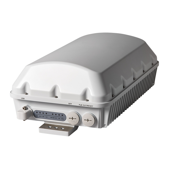
LEDs and Ports
The following figure illustrations the locations of the LEDs and ports on the
T811-CM, and the table below provides descriptions of each feature.
Use the eight LEDs to check the status of the access point and cable
modem.
Label
Description
MAC
Labels include separate addresses for the
Address
internal AP and CM.
label
location
Coaxial cable
F type, connects to the CMTS at the head
connector
end using a tap on the plant, and provides
AC POC to the T811-CM. For more
information, refer to "Powering the T811-CM
with POC."
Optional
The T811-CM is normally earth-grounded by
External
the cable strand. However, if the cable
Ground
strand is not earth grounded, then connect
Earth Point
an external earth ground to the T811-CM
using this screw-and-washer set.
Page 1 of 4
Advertisement

Related Manuals for CommScope RUCKUS T811-CM


Summary of Contents for CommScope RUCKUS T811-CM
- Page 1 Optional The T811-CM is normally earth-grounded by • RUCKUS T811-CM (Non-SFP) unit with cable strand hangers, includes External the cable strand. However, if the cable one 12-mm long stainless steel M6x1 earth ground panhead screw with...
- Page 2 CATV coax through a power passing tap. The tap is connected to F-type connector on the T811-CM as shown in AP and CM MAC Addresses, Connectors and Ground Point. Copyright © 2022 CommScope, Inc. All rights reserved. Page 2 of 4 Published March 2022, Part Number 800-73107-001 Rev B...
- Page 3 2. Attach the other end of the safety cable to the strand cable or other 3. Locate the reset button under the access plug. tighten to a torque setting of 7 in-lbs. fixed anchor. Copyright © 2022 CommScope, Inc. All rights reserved. Page 3 of 4 Published March 2022, Part Number 800-73107-001 Rev B...
- Page 4 For information on how to configure and manage the AP, refer to the RUCKUS Indoor Access Point User Guide, available from http:// docs.commscope.com/?docs-box. Copyright © 2022 CommScope, Inc. All rights reserved. Page 4 of 4 Published March 2022, Part Number 800-73107-001 Rev B...
Need help?
Do you have a question about the RUCKUS T811-CM and is the answer not in the manual?
Questions and answers