Advertisement
Quick Links
T750SE Access Point
Quick Setup Guide
NOTE: The minimum software revision for the T750SE is ZoneDirector
(ZD) 10.4.1 or later, or SmartZone (SZ) 5.2 or later, or standalone AP
firmware 114.X or later.
This Quick Setup Guide provides step-by-step instructions on how to field-
install the RUCKUS WIRELESS T750SE access point (AP). For detailed
information on planning the installation, performing a site survey, and
operating the T750SE, refer to the RUCKUS WIRELESS Outdoor Access Point
User Guide, available at https://support.ruckuswireless.com.
WARNING! Only trained and qualified personnel should be allowed to
install, replace, or service this equipment.
WARNING! Installation of this equipment must comply with local and
national electrical codes.
CAUTION! Make sure that you form a 80mm - 130mm (3"-5") drip loop
in any cable that is attached to the AP or the building. This will prevent
water from running along the cable and entering the AP or the building
where the cable terminates.
CAUTION! Be sure that grounding is available and that it meets local
and national electrical codes. For additional lightning protection, use
lightning rods and lightning arrestors.
CAUTION! Make sure that proper lightning surge protection
precautions are taken according to local electrical code.
WARNING! RUCKUS WIRELESS strongly recommends that you wear eye
protection before mounting the T750SE.
This Guide in Other Languages
• 请从以下网站获得该指南的简体中文版
https://
support.ruckuswireless.com.
• Vous trouverez la version française de ce guide à l'adresse suivante
https://support.ruckuswireless.com.
• このガイドの日本語版は
https://support.ruckuswireless.com
ください。
• 이 가이드의 한국어 버전은 웹 사이트
(https://
support.ruckuswireless.com) 에서 확인하시기 바랍니다.
• Veja a versão em português (Brasil) deste guia em
support.ruckuswireless.com.
• Puede ver la versión en español (América Latina) de esta guía en
https://support.ruckuswireless.com.
Copyright
©
2020 CommScope, Inc. All rights reserved.
Published July 2020, Part Number 800-72283-001 Rev B
Before You Begin
Before deploying RUCKUS WIRELESSs products, please check for the latest
software and the release documentation.
• Release Notes and other user documentation are available at
support.ruckuswireless.com/documents.
• Software upgrades are available at
software.
• Software license and limited warranty information are available at
http://support.ruckuswireless.com/warranty.
Before deploying your RUCKUS WIRELESS Access Point, verify that all
items listed in Package Contents are included in the package. If any item
is damaged or missing, notify your authorized RUCKUS WIRELESS sales
representative. Also, make sure that you have the required hardware
and tools.
Required Hardware and Tools
• 1/2" (13 mm) flat-blade screwdriver or equivalent
• No. 2 Phillips screwdriver
• Small flat-blade screwdriver
• Torque wrench or torque screwdriver with sockets
• Long-nose pliers
• Electrical wire stripping and terminal crimping pliers
• Pipe, pole or a sturdy flat surface
• Electric drill with drill bits and customer-supplied wall anchors, flat
washers, and hex nuts for flat-surface mount
Package Contents
A complete T750SE field installation package includes all of the items listed
below :
• T750SE Access Point
• M25 data cable gland extender
• Three M25 data cable glands
• Outdoor AP Mounting Bracket kit
• One ground wire with lug
• Cloud Management Statement
• Cable gland extender gasket
• AC Connector
• Zipcord cable gland grommet
• Four 1/2" (12.7 mm) wide adjustable clamps, 2.5" (63.5 mm) diameter,
for main mounting bracket on smaller poles
• Safety cable kit
• Service Level Agreement/Limited Warranty Statement
• Declaration of Conformity
• Regulatory Statement
• RUCKUS WIRELESS AP Getting Started Guide
• This Quick Setup Guide
でご覧
Mounting Instructions
https://
Connecting and Sealing the RJ-45 Cables
The T750SE may use zero, or one or two RJ-45 cables, one for Ethernet
when configured as a Root AP (RAP), and another when the T750SE is
supplying PoE out to a peripheral device, such as a small cell or micro cell
radio, and zero when using the SFP as a backhaul alternate with AC power.
When the T750SE uses RJ-45 cables, connect and seal the cables using the
M25 data cable glands as shown in Figure 2.
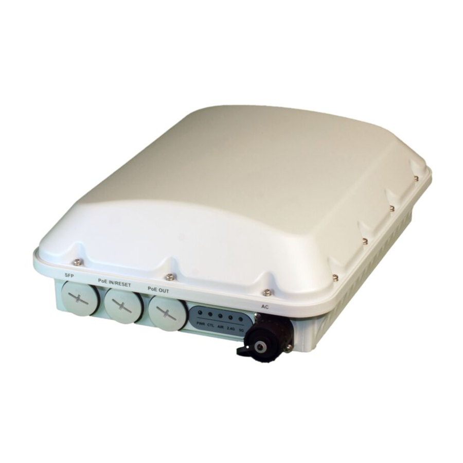
FIGURE 1 T750SE AP PoE IN and PoE OUT ports
http://
http://support.ruckuswireless.com/
1. SFP port
2. PoE IN
WARNING! Do not use any PoE injector not tested and approved by
RUCKUS WIRELESS to power the T750SE Access Point.
WARNING! Do not plug PoE IN power into the PoE OUT port. See Figure
1.
1. Feed the end of the cable through the gland dome, rubber grommet,
clamping ring assembly and cable gland base, as shown in Figure 2.
3. PoE OUT
4. AC port
NOTE: Do not seat the clamping ring and rubber grommet into the
cable gland base until the cable gland base has been torqued to
specifications.
Page 1 of 7
Advertisement

Related Manuals for CommScope RUCKUS


Summary of Contents for CommScope RUCKUS
- Page 1 • No. 2 Phillips screwdriver information on planning the installation, performing a site survey, and • Small flat-blade screwdriver operating the T750SE, refer to the RUCKUS WIRELESS Outdoor Access Point • Torque wrench or torque screwdriver with sockets User Guide, available at https://support.ruckuswireless.com.
- Page 2 2. Use four 1/4 - 28 bolt and washer sets (1) to mount the U-joint bracket (2) to the mounting bracket (3). Tighten the bolts to 9.5 N.m (84 in-lbs). Copyright © 2020 CommScope, Inc. All rights reserved. Page 2 of 7 Published July 2020, Part Number 800-72283-001 Rev B...
- Page 3 3 N.m (27 in-lbs) or per manufacturer’s specifications. AP bracket. Loosely assemble the AP bracket to the linkage bracket using the M8 bolt, washer and nut set. Copyright © 2020 CommScope, Inc. All rights reserved. Page 3 of 7 Published July 2020, Part Number 800-72283-001 Rev B...
- Page 4 NOTE: Beamflex is not available with external antennas. Copyright © 2020 CommScope, Inc. All rights reserved. Page 4 of 7 Published July 2020, Part Number 800-72283-001 Rev B...
- Page 5 Make sure that the final wrap is approximately flush with the cable coupling nut, and then cut the sealing tape. Copyright © 2020 CommScope, Inc. All rights reserved. Page 5 of 7 Published July 2020, Part Number 800-72283-001 Rev B...
- Page 6 12 mm (0.5 in.) past the sealing tape installed in Step 5: Wrapping the Main Sealing Tape on page 5. Copyright © 2020 CommScope, Inc. All rights reserved. Page 6 of 7 Published July 2020, Part Number 800-72283-001 Rev B...
-
Page 7: Troubleshooting
ARRIS, the ARRIS logo, COMMSCOPE, RUCKUS, RUCKUS WIRELESS, the Ruckus the diameter of the AC cable that you are using. logo, and the Big Dog design are trademarks of CommScope, Inc. and/or its affiliates. Wi-Fi Alliance, Wi-Fi, the Wi-Fi logo, Wi-Fi Certified, the Wi-Fi 7. -
Page 8: Federal Communications Commission Notices
Medical Statement Ruckus Wireless Access Points shall only be used in ME systems where the intended EM ENVIRONMENT does NOT does not rely on th e WLAN radio link for BASIC SAFETY or ESSENTIAL PERFORMANCE of the ME SYSTEM. - Page 9 EU Declaration of Conformity This declaration of conformity is issued under the sole responsibility of the manufacturer (or installer): Ruckus Wireless, Inc. - 350 West Java Drive, Sunnyvale, CA 94089 USA +1-650-265-4200 The object of the declaration is in conformity with Directive 2014/53/EU of the European Parliament and of the Council of 16 April 2014 and Directive 2011/65/EU of the European Parliament and of the Council of 8 June 2011 on the harmonisation of the laws of the Member States relating to the making available on the market of radio equipment.
- Page 10 [Swedish] bestämmelser som framgår av direktiv 2014/53/EU. Íslenska Hér með lýsir Ruckus Wireless yfir því að Radio LAN er í samræmi við grunnkröfur og aðrar kröfur, sem gerðar eru í tilskipun 2014/53/EU. [Icelandic] Norsk Ruckus Wireless erklærer herved at utstyret Radio LAN er i samsvar med de grunnleggende krav og øvrige relevante krav i direktiv 2014/53/EU.
- Page 11 Page 4 T750 & T750SE, Access Point Installation Addendum When the frequency band 5150 – 5250 MHz is used outdoors in the U.S.A, the FCC mandates that the energy radiated above 30° from the horizon remains below 21 dBm EIRP. This can be maintained during installation using the following guidance. When the device is installed level to the horizon, (i.e.
Need help?
Do you have a question about the RUCKUS and is the answer not in the manual?
Questions and answers