Sign In
Upload
Manuals
Brands
Azbil Manuals
Transmitter
JTS922S
Azbil JTS922S Manuals
Manuals and User Guides for Azbil JTS922S. We have
1
Azbil JTS922S manual available for free PDF download: User Manual
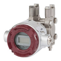
Azbil JTS922S User Manual (196 pages)
Advanced differential pressure and pressure transmitter
Brand:
Azbil
| Category:
Transmitter
| Size: 9 MB
Table of Contents
Table of Contents
9
Chapter 1 Functionality, Configuration, and Structure of this Device and Commstaff
13
Functionality and Configuration of this Device
13
Part Names
14
Indicators (Optional)
16
Commstaff Functionality and Configuration
19
Introduction
19
Precautions
19
Configuration of Commstaff and Peripheral Devices
19
Usage Environment
19
Conditions for Connected Devices
20
Chapter 2 Installation of this Device
21
Installation Location Selection Criteria
21
General Installation Conditions
21
Explosion-Proof Transmitter Installation Criteria
21
Equipment Use Conditions
24
Installation
25
Installation Dimensions
25
Installation Location
25
Transmitter Body Installation
25
Connecting the Wetted Part of a Flange Type or Remote Seal Type to the Process
29
Precautions When Attaching FEP Protective Film
32
Fit-Tank Attachment (JTE Model)
35
1/2B Remote Attachment (JTE/JTH Model)
40
To a Flanged Transmitter (Models JTE, JTH, JTS, and JTC)
42
Piping
46
Flow Rate Measurement Piping (JTD Model)
46
Pressure Measurement Piping (JTD/JTG/JTA Model)
51
Liquid Level Measurement Piping (JTD/JTG Model)
54
Liquid Level Measurement Piping (JTC Model)
59
Electrical Wiring
61
General Wiring
61
Wiring for Explosion-Proof Models
64
Changing the Position of the Process Connection Port
66
Changing the Height of the Process Connection Port (JTD/JTG/JTA/JTC Model)
66
Chapter 3 Starting and Stopping this Device
67
Operation Preparations
68
Communicator Connection
68
Settings Confirmation
69
Measurement Using the JTD Model
72
Flow Rate Measurement
72
Pressure Measurement
76
Open Tank and Sealed Tank (Dry Leg) Liquid Level Measurement
80
Sealed Tank (Wet Leg) Liquid Level Measurement
84
Measurement Using the JTG/JTA Model
88
Pressure Measurement
88
Liquid Level Measurement
92
Measurement Using the JTC Model
95
Liquid Level Measurement
95
Measurement Using the JTE Model
98
Liquid Level Measurement
98
Flow Rate Measurement
100
Measurement Using the JTH/JTS Model
101
Liquid Level and Pressure Measurement
101
Zero Adjustment Based on Actual Level During Liquid Level Measurement
104
Zero/Span Adjustment Based on Range-Equivalent Input Pressure
104
External Zero Adjustment (Optional Function)
105
Calculating the Setting Range During Liquid Level Measurement
107
Open Tank and Sealed Tank (Dry Leg or Remote Seal) Setting Range
107
Sealed Tank (Wet Leg or Remote Seal) Setting Range
117
Advanced Diagnostics (Optional )
125
Pressure Frequency Index
125
Standard Deviation
129
Out-Of-Range Pressure Event Count
131
Chapter 4 Maintenance and Troubleshooting of this Device
133
Assembly and Disassembly of this Device
133
Cautions During Assembly and Disassembly
133
Attaching and Detaching the Case Cover
134
Attaching and Detaching the Main Unit Cover (JTD, JTG, JTA, and JTC)
135
Cleaning the Device
137
Replacement of Electronics Module
137
Calibration of the Setting Range and Output Signal
141
Setting Range Calibration Using a Reference Input Device
141
Output Signal Calibration
143
Calibration Value Restoration and History Functions
144
Restoring the Factory Calibration Value
144
Diagnostics History Display
144
Zero Calibration Internal Data
146
Troubleshooting
147
Insulation Resistance Test and Withstand Voltage Test
152
A1 Diagnosis of Clogging in the Connecting Pipe Using the Pressure Frequency Index
153
A1-1 Principle
153
A2 Configuration Using a Pressure Gauge
155
A2-1 Clogging and the Pressure Frequency Index
155
A2-2 Points to Note Regarding the Diagnosis of Clogging
155
A2-3 Parameter Configuration Procedures
156
A2-4 Configuration Procedures
157
A2-4-1 Preparation
157
A2-4-2 Acquisition of Index Values under Normal Operating Conditions
157
A2-4-3 Clogging Simulation Test
158
A2-4-4 Judging the Possibility of Diagnosis
159
A2-4-5 Setting of the Diagnosis Alarm
160
A2-4-6 Parameter Adjustment
161
A2-4-7 Clogging Simulation Test Cannot be Conducted
163
A3 Setting Using a Differential Pressure Gauge
164
A3-1 Clogging and Pressure Frequency Index
164
A3-2 Points to Note Regarding the Diagnosis of Clogging
164
A3-3 Parameter Configuration Procedures
166
A3-4 Configuration Procedures
168
A3-4-1 Preparation
168
A3-4-2 Acquisition of the Index Values under Normal Operating Conditions
168
A3-4-3 Clogging Simulation Test
168
A3-4-4 Judging the Possibility of Diagnosis
170
A3-4-5 Setting the Diagnosis Alarm
172
A3-4-6 Parameter Adjustment (for Both-Side Clogging Diagnosis
173
A3-4-7 Parameter Adjustment (for Single Side Clog Diagnosis
175
A3-4-8 Clogging Simulation Test Cannot be Conducted
176
A4 Setting Using a Level Meter
177
A4-1 Clogging and the Pressure Frequency Index
177
A4-2 Points to Note Regarding the Diagnosis of Clogging
177
A4-3 Parameter Configuration Procedures
178
A4-4 Configuration Procedures
179
A4-4-1 Preparation
179
A4-4-2 Acquisition of the Index Values under Normal Operating Conditions
179
A4-4-3 Clogging Simulation Test
180
A4-4-4 Judging the Possibility of Diagnosis
181
A4-4-5 Setting of the Diagnosis Alarm
182
A4-4-6 Parameter Adjustment
182
A4-4-7 Clogging Simulation Test Cannot be Conducted
184
A5 Supplemental Description of Parameters
185
A5-1 Pressure Frequency Filter Constant
185
A5-2 Sensor Selection
185
A5-2-1 P Sampling Interval
185
A5-2-2 Sensor Type
186
Advertisement
Advertisement
Related Products
Azbil JTS940S
Azbil JTL321
Azbil JTL322
Azbil JTL330
Azbil JTL331
Azbil JTD910S
Azbil JTD920S
Azbil JTD930S
Azbil JTD931S
Azbil JTG980S
Azbil Categories
Controller
Control Unit
Measuring Instruments
Transmitter
Security Sensors
More Azbil Manuals
Login
Sign In
OR
Sign in with Facebook
Sign in with Google
Upload manual
Upload from disk
Upload from URL