
Related Manuals for FabiaTech FB2701


Summary of Contents for FabiaTech FB2701
- Page 1 FabiaTech Corporation IPC Solution Website: http://www.fabiatech.com Email: support@fabiatech.com ISA CPU Card Low Power Series FB2701 User’s Manual JULY 2019 Version: 1.1 Part Number: FB2701...
- Page 2 FabiaTech shall not be reliable for technical or editorial errors or omissions, which may occur in this document. FabiaTech shall not be reliable for any indirect, special, incidental or consequential damages resulting from the furnishing, performance, or use of this document.
-
Page 3: Table Of Contents
Table of Contents FB2701 User’s Manual ......................i Chapter 1 Introducing the FB2701 CPU Card ................1 Overview..........................1 Series Comparison Table .......................2 Layout............................3 Specifications..........................4 Packing List ..........................5 Chapter 2 Hardware Installation ....................7 Before Installation ........................7 Hardware Features.........................8 DIMM1: DIMM Socket for DDR3L SDRAM Modules ........9 ... - Page 4 Keyboard Convention ..................25 Main Setup ..........................26 Advanced Setup........................27 ACPI settings ......................28 CPU Configuration....................30 IDE Configuration....................32 USB Configuration .....................34 SMART Settings....................37 IT8786 Super IO Configuration.................38 Hardware Health Configuration..............41 Wake Configuration ..................42 Realtek PCIe GBE Family Controller (MAC) ..........43 ...
- Page 5 Watchdog Timer Setting ..................67 Watchdog Timer Enabled ................68 Watchdog Timer Trigger ..................68 Watchdog Timer Disabled................68 Chapter 6 Technical Reference ....................69 Technical Reference......................69 Physical and Environmental ................69 Real-Time Clock and Non-Volatile RAM ............69 CMOS RAM Map....................71 ...
-
Page 7: Chapter 1 Introducing The Fb2701 Cpu Card
Chapter 1 Introducing the FB2701 CPU Card Overview The FB2701 is an AMD® G-Serial T40E low power all–in-one ISA CPU card. This user’s manual provides information on the physical features, installation, and BIOS setup. Built to unleash the total potential of the AMD® G-Serial T40E Processor, the FB2701 is an ISA CPU card capable of handling today’s demanding requirements. -
Page 8: Series Comparison Table
FabiaTech Corporation Series Comparison Table Model FB2701 Processor AMD® G-Serial T40E 1.0 GHZ Memory DDR3L-1066 204 Pin So-DIMM*1 4GB (Max.) Display VGA/LVDS S-Chipset AMD Fusion Controller HUB A55E Multi I/O Port Three RS232 & One RS232/RS422/RS485 USB 2.0 Port Four... -
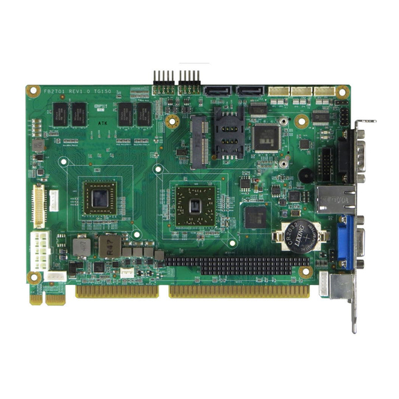
Page 9: Layout
FabiaTech Corporation Layout CN11 CN10 CN12 CN13 BUS1 CN14 CN15 CN16 CN17 DIMM1 CN18... -
Page 10: Specifications
FabiaTech Corporation Specifications Processor & Memory – AMD® G-Serial T40E 1.0 GHZ (512KB L2 Cache For Per Core) Dual Core Low Power Processor One 204 pin So-DIMM socket support 2G to 4G DDR3L RAM module I/O Outlets – One 10/100/1000 base-TX Ethernet LAN port with RJ45 VGA connector with DB15 and LVDS LCD Connector 4 USB ports (2.0) and providing AC97 audio function... -
Page 11: Packing List
• If the cable(s) you use to install the FB2701 is not supplied from us, please make sure the specification of the cable(s) is compatible with the FB2701. Note: after you install the FB2701, it is recommended that you keep the diskette or CD that contains drivers and document files, document copies, and unused cables in the cartoon for future use. - Page 12 FabiaTech Corporation...
-
Page 13: Chapter 2 Hardware Installation
FabiaTech Corporation Chapter 2 Hardware Installation This chapter introduces the system connectors & jumper settings, and guides you to apply them for field application. Before Installation Before you install the system, make sure you follow the below descriptions. 1. Before removing the CPU card from its anti-static bag, wear an anti-static strap to prevent the generation of Electricity Static Discharge (ESD). -
Page 14: Hardware Features
FabiaTech Corporation Hardware Features The following lists the connectors and jumpers to install the FB2701. Item Description SATA Connector (7-Pin) CN1, CN2 COM1(CN8-DB9)-RS232/422/485 port, COM2(CN5)/ COM3(CN4)/ COM4(CN3)– RS232 CN8, CN3, CN4, CN5 (JST 2*5- Pin 2.0mm) SIM Card Socket for GPRS PCIe Mini Card socket for Wireless, GPRS or m-SATA module HD Audio Connector (IDC 2*6 - Pin 2.0mm ) -
Page 15: Dimm1: Dimm Socket For Ddr3L Sdram Modules
FabiaTech Corporation DIMM1: DIMM Socket for DDR3L SDRAM Modules The 204 pin So-DIMM socket supports 2GB to 4GB of DDR3L RAM modules. DIMM1 CN18 CN18: CFAST Socket The CFAST Compact Flash socket CN18 (on the solder side) is support CFAST Compact Flash. -
Page 16: J1 & J2: Usb Port & Connector Header
FabiaTech Corporation J1 & J2: USB Port & Connector Header The CPU card supports four USB port. Any USB device can be attached to USB ports with plug-and-play supported, J1 and J2 are 10-pin connectors. Use the inclued USB adapter cable and (or) FB4706 Audio board (Option) can attach up to 4 USB devices. -
Page 17: Cn17 & Cn16: Keyboard/Mouse Connector
FabiaTech Corporation CN17 & CN16: Keyboard/Mouse Connector CN17 is a standard PS/2 type keyboard connector and any PS/2 type keyboard can plug into CN17 directly without extra adapter cable. Use the keyboard + mouse adapter cable (optional), you can connect keyboard and mouse simultaneously. -
Page 18: J4: Cpu Or System Fan Connector
FabiaTech Corporation J4: CPU or System Fan Connector CN11 CN10 Signal CN12 Ground CN13 +12V BUS1 CN14 Speed-In CN15 CN16 CN17 JP2: Clear CMOS Data You can use JP2 to clear CMOS data. The CMOS stores information like system date, time, boot up device, password, IRQ…... -
Page 19: Cn7 & Cn6: Pcie Mini Card Or M-Sata Module & Sim Card
FabiaTech Corporation CN7 & CN6: PCIe Mini Card or m-SATA Module & SIM Card This CPU card supports PCIe mini card socket; you may extend additional PCIe mini card module and SIM card or m-SATA module to card. Connect to the antenna cable to GPRS or Wireless LAN module and install the SIM card for GPRS. -
Page 20: Bus1: Pc/104 Bus Connectors
I/O Port resource; when set ITE8888 ISA Decode is Positively decode, if you add on the I/O card or memory card to FB2701.You can refer to Chapter 6 Technical Reference “ Configure Positively Decode I/O port & Memory ”... -
Page 21: Bus4: Pciex1
PRSNT1# +12V +12V +12V +12V +12V Ground Ground SMBCLK SMBDATA Ground +3.3V +3.3V +3.3V +3.3 VSB PWRGD WAKE# Ground PCIECLK+ Ground PCIECLK- PCIETX+ Ground PCIETX- PCIERX+ Ground PCIERX- Ground Ground NOTE: The PCIe*1 need use BP04IE backplane of FabiaTech Product. -
Page 22: Cn9: External Bus Connector For Audio Function
The CN4, CN6, and CN5 connectors on FB4706x are 2-way Line-In, mono Microphone input, and 2-way Lineout respectively. You can connect J1 (Audio), CN2 (USB) cable from FB2701 CN9 and J1 or J2. The following figure shows these Audio connectors on FB4706x board:... -
Page 23: Cn14: Auxiliary Power Connector (For Atx Power Supply Only)
FabiaTech Corporation CN14: Auxiliary Power Connector (for ATX Power Supply Only) CN14 is the power connector for FB2701 is used with stand-alone applications. CN14 Note: This power connector is ideal for CN11 standalone applications. CN10 CN12 Signal Signal CN13 PS_ON... -
Page 24: J3 & Bz1: Multi Function Header And On-Board Buzzer
PW LED- CN15 CN16 CN17 LAN LED+ LAN LED- Note: The PW Button+/- are two signals in the J3, which is connected to PWR-SW (Power Button Switch); It’s Pushing the PWR-SW button once will switch the FB2701 on or off. -
Page 25: Chapter 3 Installing Vga & Lcd Display
The following shows the block diagram of using FB2701 for LVDS LCD module. LCD Panel Block Diagram The diagram shows that FB2701 needs components to be linked with a LCD Module. NOTE: Be careful with the pin orientation when installing connectors and the cables. A wrong connection can easily destroy your LCD module. -
Page 26: Vga Display (Cn13)
FabiaTech Corporation VGA Display (CN13) The FB2701 supports a VGA colored monitor. It can be connected to create a compact video solution for the industrial environment. 254MB simulated VRAM allows a maximum VGA resolution of 1920X1080 with 32 bit at 60Hz. -
Page 27: Cn12 & Cn11: Lvds Connector And Power Connector
LVDS_CK+ LVDS_CK- Ground LDP0_AUX+ 15 LTDP0_AUX- Ground LTDP0_HP0 Ground Ground Ground Ground 27 LVDS_+3.3V 28 LVDS_+3.3V 29 LVDS_+3.3V 30 LVDS_+3.3V NOTE: If any trouble occurs when connecting FB2701 with LCD panels, you could contact technical support division of FabiaTech Corporation. - Page 28 FabiaTech Corporation...
-
Page 29: Chapter 4 Bios Setup
FabiaTech Corporation Chapter 4 BIOS Setup This chapter describes the BIOS setup. Overview BIOS are a program located on a Flash memory chip on a circuit board. It is used to initialize and set up the I/O peripherals and interface cards of the system, which includes time, date, hard disk drive, the ISA bus and connected devices such as the video display, diskette drive, and the keyboard. -
Page 30: Bios Functions
FabiaTech Corporation BIOS Functions On the menu, you can perform the following functions 1. Main 2. Advanced ACPI Settings CPU Configuration IDE Configuration USB Configuration SMART Settings IT8786 Super IO Configuration IT8786 HW Monitor WAKE Configuration IT8888 Configuration 3. Chipset... -
Page 31: Keyboard Convention
FabiaTech Corporation Keyboard Convention On the BIOS, the following keys can be used to operate and manage the menu: Function [↑][↓] The Up and Down keys allow you to select item. [←][→] The Left and Right keys allow you to select screen. -
Page 32: Main Setup
FabiaTech Corporation Main Setup This section describes BIOS version information and basic system hardware configuration. If the CPU board is already installed in a working system, you will not need to select this option anymore. System Date & Time Setup Highlight the <Date>... -
Page 33: Advanced Setup
FabiaTech Corporation Advanced Setup Select the Advanced tab from the setup screen to enter the Advanced BIOS Setup screen. You can select any of the items in the left frame of the screen, such as USB Configuration, to go to the sub menu for that item. You can display an Advanced BIOS Setup option by highlighting it using the <Arrow>... -
Page 34: Acpi Settings
FabiaTech Corporation ACPI settings This filed specifies allow you set this value to utilize the ACPI (Advanced Configuration and Power Interface) specification. Enabled ACPI Auto Configuration This item allows users to enable or disable BIOS ACPI Auto Configuration. Available Options: Disabled, Enabled... - Page 35 FabiaTech Corporation ACPI Sleep State This item allows users to select the highest ACPI sleep state the system will enter when the SUSPEND button is pressed. Available Options: Suspend Disabled and S1 Only (CPU Stop Clock). Default setting: Suspend Disabled Lock Legacy Resources This item allows users to enable or disable Lock of Legacy Resources.
-
Page 36: Cpu Configuration
FabiaTech Corporation CPU Configuration The Item Display CPU Information, like CPU speed and L1/L2 cache and support function, you can use this screen to select options for the CPU information. Use the up and down <Arrow> keys to select an item. Use the <Plus> and <Minus> keys to change the value of the selected option. - Page 37 FabiaTech Corporation PPC Adjustment This field provides to adjust _PPC objects. Available Options: PSTATE0, and PSTATE2 Default setting: PSTATE0 NX Mode This field allows the users to enable or disable the No-executed page Protection functions. Available Options: Disabled, and Enabled...
-
Page 38: Ide Configuration
FabiaTech Corporation IDE Configuration You can use this screen to select options for the SB SATA Configuration. - Page 39 FabiaTech Corporation SB SATA Configuration OnChip SATA Channel This item allows users to enable or disable SATA Controller. Available Options: Disabled, and Enabled Default setting: Enabled OnChip SATA Type Select a configuration for SATA controller. Install Windows XP in AHCI mode need to use the F6 Method pre-installed AHCI driver, if you select Legacy IDE mode, you do not need to pre-install.
-
Page 40: Usb Configuration
FabiaTech Corporation USB Configuration You can use this screen to select options for the USB Configuration. Legacy USB Support Legacy USB Support refers to the USB mouse and USB keyboard support. Normally if this option is not enabled; any attached USB mouse or USB keyboard will not become available until a USB compatible operating system is fully booted with all USB drivers loaded. - Page 41 FabiaTech Corporation USB Mass Storage Driver Support Mass storage device emulation type. If the emulation FDD, recommended formatted as FAT32 format. Available Options: Disabled, and Enabled Default setting: Enabled USB transfer time-out The time-out value for control, bulk, and interrupt transfers.
- Page 42 FabiaTech Corporation Device power-up delay > Select “Manual“ Device Power-Up delay in second Delay range is 1...40 seconds, in one second increments Available Options: 1, 5, 10, 20, 30, and 40 Sec Default setting: 5 Sec Generic Storage Device 1.01 Mass storage device emulation type.
-
Page 43: Smart Settings
FabiaTech Corporation SMART Settings SMART Self TEST Run SMART Self TEST on all HDD during POST. Available Options: Disabled, and Enabled Default setting: Disabled... -
Page 44: It8786 Super Io Configuration
FabiaTech Corporation IT8786 Super IO Configuration This section describes the function of Super I/O settings. Serial Port 0 Configuration These fields select the I/O port address for Serial port 0. - Page 45 FabiaTech Corporation Serial Port 0 This item allows users to select the enable or disable Serial port. Available Options: Enabled, and Disabled. Default setting: Enabled Device Settings Serial Port0: IO=3F8; IRQ=IRQ4 Transfer Mode Setting This item allows users can select RS-232, RS-422 and RS-485 of select COM1.
- Page 46 FabiaTech Corporation Serial Port 1/2/3 This item allows users to select the enable or disable Serial port of select COM2 /COM3 /COM4. Available Options: Enabled, and Disabled. Default setting: Enabled Device Settings Serial Port1: IO=2F8; IRQ=IRQ3 Serial Port2: IO=3E8; IRQ=IRQ10...
-
Page 47: Hardware Health Configuration
FabiaTech Corporation Hardware Health Configuration On the Hardware Monitor Setup screen, you can monitor the system temperature1, System voltage, and VBAT voltage…... -
Page 48: Wake Configuration
FabiaTech Corporation Wake Configuration Onboard PCIE LAN PXE ROM This field specifies the PXE boot ROM of the onboard LAN chip. Available Options: Disabled, and Enabled Default setting: Disabled Wake ON Lan This item is can select Enabled to integrated LAN to wake up the system. -
Page 49: Realtek Pcie Gbe Family Controller (Mac)
FabiaTech Corporation Realtek PCIe GBE Family Controller (MAC) On the LAN Information screen, you can see the LAN Chipset information, when setting Launch PXE OpROM Policy to UEFI Only of CSM Boot. -
Page 50: Ite8888 Setting
FabiaTech Corporation ITE8888 Setting ITE 8888 ISA Decode These fields are used for the Select Subtractive or positive decode IO Space. Available Options: Subtractive Decode, Positively Decode Default setting: Positively Decode Memory Hole 15MB- 16MB This field specifies the location of an area of memory that cannot be addressed on the ISA bus. - Page 51 FabiaTech Corporation ISA IO Decode Space This option allows you to select the IO port space for add on card on FB2701. Decode I/O Space 0~5 These fields are used for the enable configuration and the positive decode IO Space.
-
Page 52: Ite8888 Isa Decode Memory
FabiaTech Corporation ITE8888 ISA Decode Memory This option allows you to select the Memory space to add on card on FB2701. Decode Memory Space 0~3 These fields are used for the enable configuration and the positive decode Memory Space. Available Options: Disabled and Enable... -
Page 53: Chipset
FabiaTech Corporation Chipset This section describes the configuration of the board’s chipset features. • North Bridge • North Bridge LVDS Config Select • South Bridge... -
Page 54: North Bridge
FabiaTech Corporation North Bridge You can use this screen to select options for the North Bridge Configuration. Use the up and down <Arrow> keys to select an item. Use the <Plus> and <Minus> keys to change the value of the selected option. - Page 55 FabiaTech Corporation GFX Configuration On the Socket 0 Information screen, you can see the system memory information. Port 4 Control (mini-Card) The onboard LAN corresponding PCI Express port 4, the item allows users to enable or disable on board PCIe mini Card (For Wireless or GPRS).
-
Page 56: North Bridge Lvds Config Select
FabiaTech Corporation North Bridge LVDS Config Select You can use this screen to select options for the Host Bridge Configuration. Use the up and down <Arrow> keys to select an item. Use the <Plus> and <Minus> keys to change the value of the selected option. -
Page 57: South Bridge
FabiaTech Corporation South Bridge You can use this screen to select options for the South Bridge Configuration. South Bridge is a chipset on the motherboard that controls the USB, and audio function. Restore On AC Power Lose This field specifies the option controls how the PC will behave once power is restored following a power outage (or other unexpected or ungraceful shutdown). - Page 58 FabiaTech Corporation USB Configuration OHCI HC (Bus 0 Dev 18 FN 0) The USB OHCI HOST Control each of the USB ports (0~1). Enable: Enable USB 0, 1 port; Disable: Use USB port 0, 1 setting Available Options: Disabled, and Enabled...
- Page 59 FabiaTech Corporation Azalia HD Audio Audio Controller This item allows users to enable or disable Azalia Controller. Available Options: Disabled, and Enabled Default setting: Disabled...
-
Page 60: Boot
FabiaTech Corporation Boot Select the Boot tab from the setup screen to enter the Boot BIOS Setup screen. You can select any of the items in the left frame of the screen, such as Boot Device Priority, to go to the sub menu for that item. You can display a Boot BIOS Setup option by highlighting it using the <Arrow>... - Page 61 FabiaTech Corporation Quiet Boot This item allows users to enable or disable Quiet boot option. If Enable, an OEM LOGO is shown instead of POST messages. Available Options: Disabled, and Enabled Default setting: Disabled Fast Boot This field is used to activate the fast boot function of the system. When set to Enabled, boot with initialization of a minimal set of devices required to launch active boot option.
-
Page 62: Csm Parameters
FabiaTech Corporation Note: When you select a boot Option category from the boot menu, a list of devices in that category appears. For example, if the system has hard disk drives and USB storage connected, then the list will show all hard disk drives attached. - Page 63 FabiaTech Corporation Launch PXE OpROM Policy This option Controls the execution of UEFI and Legacy PXE OpROM. Available Options: Do not Launch, Legacy only, UEFI only, Leach First and UEFI First. Default setting: Do not Launch Launch Storage OpROM Policy This option Controls the execution of UEFI and Legacy Storage OpROM.
-
Page 64: Security
FabiaTech Corporation Security Security Setup provides both Administrator and User password. If you use both passwords, the Administrator password must be set first. The system can be configured so that all users must enter a password every time the system boots or when Setup is executed, using either the Administrator password or User password. - Page 65 FabiaTech Corporation Clear Old Password Select Administrator/user password item, press <Enter> and type current password, at the next dialog press <Enter> to Clear Old Password.
-
Page 66: Save & Exit
FabiaTech Corporation Save & Exit Save Changes and Exit When you have completed the system configuration changes, select this option to save the changes and Exit, so the new system configuration parameters can take effect. Discard Changes and Exit Select this option to quit without making any modifications to the system configuration. - Page 67 FabiaTech Corporation Save Changes When you have completed the system configuration changes, select this option to save your system configuration and continue. For some of the options it required to reset the system to take effect... Discard Changes When you have completed the system configuration changes, select this option to undo the previous changes.
- Page 68 FabiaTech Corporation...
-
Page 69: Chapter 5 Software Installation
FabiaTech Corporation Chapter 5 Software Installation The enclosed CD diskette includes FB2701 VGA, System, Audio, and LAN driver. To install and configure you FB2701 system, you need to perform the following steps. Install AMD Catalyst ™ Drivers WIN XP/7 32/64 Driver To install the AMD T40E driver, insert the DVD ROM into the USB DVD ROM device, and enter DRIVER>VGA>AMD_T40E>WINXP, or >WIN7. -
Page 70: Audio Driver
FabiaTech Corporation Step 9: The AMD - Catalyst Install Manager will analyze the system, and install the required files. Step10: The AMD - Catalyst Install Manager will confirm when the installation is complete. Click Finish. Step11: When prompted, click Yes to restart the system and complete the installation process. -
Page 71: Pci To Isa Bridge Drivers
FabiaTech Corporation PCI to ISA Bridge Drivers WINDOWS Driver Step 1: To install the PCI To ISA Bridge driver, insert the CD ROM into the CD ROM device, and enter DRIVER>SysChip >ITE8888 >WIN. If your system is not equipped with a CD ROM device, copy the PCI To ISA Bridge driver from the CD ROM to a CF. -
Page 72: Watchdog Timer
This section describes how to use the Watchdog Timer, including disabled, enabled, and trigger functions. The FB2701 is equipped with a programmable time-out period watchdog timer. You can use your own program to Enabled the watchdog timer. Once you have enabled the watchdog timer, the program should trigger the I/O every time before the timer times out. -
Page 73: Watchdog Timer Setting
FabiaTech Corporation Watchdog Timer Setting The watchdog timer is a circuit that may be used from your program software to detect system crashes or hang-ups. The watchdog timer is automatically disabled after reset. Once you have enabled the watchdog timer, your program must trigger the watchdog timer every time before it times out. -
Page 74: Watchdog Timer Enabled
FabiaTech Corporation Watchdog Timer Enabled To enable the watchdog timer, you have to output a byte of timer factor to the watchdog register whose address is 2eh and data port is 2fH. The following is a Demo program, which demonstrates how to enable the watchdog timer and set the time- out period at 28 seconds. -
Page 75: Chapter 6 Technical Reference
Relative humidity 0 % to 90 % non-condensing Real-Time Clock and Non-Volatile RAM The FB2701 contains a real-time clock compartment that maintains the date and time in addition to storing configuration information about the computer system. It contains 14 bytes of clock and control registers and 114 bytes of general purpose RAM. - Page 76 FabiaTech Corporation Address Description Minute alarm Hours Hour alarm Day of week Date of month Month Year Status register A Status register B Status register C Status register D Diagnostic status byte Shutdown status byte Diskette drive type byte, drive A and B...
-
Page 77: Cmos Ram Map
FabiaTech Corporation CMOS RAM Map Register Description 00h -10h Standard AT-compatible RTC and Status and Status Register data definitions 11h – 13h Varies Equipment Bits Number of Floppy Drives 1 Drive 2 Drives Bits Monitor Type Not CGA or MDA 01 40x25 CGA... -
Page 78: I/O Port Address Map
FabiaTech Corporation I/O Port Address Map Each peripheral device in the system is assigned a set of I/O port addresses, which also becomes the identity of the device. The following table lists the I/O port addresses used on the Industrial CPU Card. -
Page 79: Interrupt Request Lines (Irq)
FabiaTech Corporation Interrupt Request Lines (IRQ) There are a total of 15 IRQ lines available on the Industrial CPU Card. Peripheral devices use interrupt request lines to notify CPU for the service required. The following table shows the IRQ used by the devices on the Industrial CPU Card. -
Page 80: Serial Ports
FabiaTech Corporation Serial Ports The ACEs (Asynchronous Communication Elements ACE1 to ACE2) are used to convert parallel data to a serial format on the transmit side and convert serial data to parallel on the receiver side. The serial format, in order of transmission and reception, is a start bit, followed by five to eight data bits, a parity bit (if programmed) and one, one and half (five-bit format only) or two stop bits. - Page 81 FabiaTech Corporation Bit 2: Enable Receiver Line Status Interrupt (ELSI) Bit 3: Enable MODEM Status Interrupt (EDSSI) Bit 4: Must be 0 Bit 5: Must be 0 Bit 6: Must be 0 Bit 7: Must be 0 Interrupt Identification Register (IIR) Bit 0: “0”...
- Page 82 FabiaTech Corporation Bit 6: Set Break Bit 7: Divisor Latch Access Bit (DLAB) MODEM Control Register (MCR) Bit 0: Data Terminal Ready (DTR) Bit 1: Request to Send (RTS) Bit 2: Out 1 (OUT 1) Bit 3: Out 2 (OUT 2)
- Page 83 FabiaTech Corporation Bit 5: Data Set Ready (DSR) Bit 6: Ring Indicator (RI) Bit 7: Received Line Signal Detect (RSLD) Divisor Latch (LS, MS) Bit 0: Bit 0 Bit 8 Bit 1: Bit 1 Bit 9 Bit 2: Bit 2...
-
Page 84: Configure Positively Decode I/O Port & Memory
~177 HEX space and ROM/RAM memory space is D000:0 ~D3FF:0 (16K), the following steps are for you to set up the I/O or memory resources manually. 1. Booting the FB2701 CPU card and go into the BIOS CMOS SETTUP > Advanced > IT8888 Settings >, then select ISA Decode IO Space. - Page 85 Note: 1. If the wrong selection of I/O ports or memory space conflicts on the FB2701 CPU card, you can clean CMOS setup by the JP2. 2. The step1 and Step 2 is for I/O add-on board, and step 3 is for ROM/RAM...
-
Page 86: Appendix
FabiaTech Corporation Appendix Dimension...
Need help?
Do you have a question about the FB2701 and is the answer not in the manual?
Questions and answers