Advertisement
Quick Links
DO
GUIDE
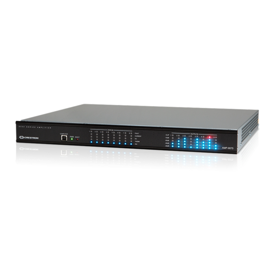
AMP(I)-8075/AMP(I)-8150
Avia
8-Channel Commercial Amplifiers
TM
The Avia™ AMP-8075, AMPI-8075, AMP-8150, and AMPI-8150 feature similar operation. For simplicity within this guide, the term "amplifier" is used for all
models except where noted.
DO
Install the Device
These devices occupy 1U of rack space. Using a #1 or #2 Phillips screwdriver, attach the included rack ears to the device, and then mount the device into the
rack using eight mounting screws (not included).
Install front rack ears.
DO
Connect the Device
Make the necessary connections as called out in the following diagrams. Connect power last.
CAUTION:
When connecting a Windows
7 or Windows 8 computer to the COMPUTER port for the first time, make sure the computer has a live connection
®
to the Internet. For more information, refer to Answer ID 5745 in the Online Help section of the Crestron website (support.crestron.com).
CAUTION:
Keep the device unplugged until all of the input, network, and speaker wiring is complete.
CAUTION:
Check the speaker wires for shorts and frayed wiring around the SPEAKER OUTPUTS connectors.
NOTE:
Ensure the unit is properly grounded by connecting the chassis ground lug to an earth ground (building steel).
NOTE:
To prevent overheating, do not operate this product in an area that exceeds the environmental temperature range listed in the table of specifications
on the product web page.
Front Panel
COMPUTER:
Direct computer connection to device
Rear Panel
LINE INPUTS 1–8:
From DSP outputs
SPEAKER OUTPUTS:
To speakers
Install rear rack ears.
POWER:
From ac power outlet
BRIDGE CH
ODD
EVEN
8 Ω ONLY
LAN:
Ground
10/100/1000BASE-T Ethernet to LAN
DO
Check the Box
QUANTITY
PRODUCT
2
Bracket, Rack Ear, 1U
2
Bracket, Rear Mounting
1
Cable, USB 2.0, A - B, 6' (1.83 m)
8
Connector, 2-Pin
8
Connector, 3-Pin
AMP-8075 and AMP-8150 Only
1
Fuse, 10.0 A, Time Lag, 1.25" x 0.25", Ceramic Cartridge, 250 V
1
Power Cord, 6' 7" (2 m)
AMPI-8075 and AMPI-8150 Only
1
Fuse, 6.3 A, Time Lag, 5 x 20 mm, Ceramic Cartridge, 250 V
1
Power Cord
Speaker Connections
The speaker outputs can be wired conventionally, or they can be bridged to deliver higher power to a speaker. Refer to the following diagrams when
connecting speakers.
WARNING:
This amplifier is capable of delivering high power to the loudspeakers. Please use caution and adequate ear protection if listening to content at
high volume levels, as continued exposure to high sound pressure levels can cause permanent hearing impairment or loss.
Conventional wiring
Bridged wiring
1
2
1
Speakers are bridged with the Avia Audio tool, which can be downloaded from www.crestron.com/software. The possible bridging combinations are Output 1
& Output 2, Output 3 & Output 4, Output 5 & Output 6, and Output 7 & Output 8.
NOTE:
Only 8 ohm speakers can be bridged.
Fuse Replacement
If the amplifier does not power up when the power is turned on, the fuse may need to be replaced. The fuse holder is located on the rear panel, next to the
power switch. To replace the fuse, perform the following procedure:
1. Disconnect power to the amplifier.
2. Use a flat-head screwdriver to push in the fuse holder.
3. While pushing in the fuse holder, turn the screwdriver counterclockwise until the fuse holder pops out.
4. Remove the fuse from the fuse holder and insert a new fuse.
MODELS
REQUIRED FUSE TYPE
AMP-8075
10.0 A, Time Lag, 1.25" x 0.25",
AMP-8150
Ceramic Cartridge, 250 V
(US & Canada)
AMPI-8075
Fuse, 6.3 A, Time Lag, 5 x 20 mm,
AMPI-8150
Ceramic Cartridge, 250 V
(International/220-240 VAC)
CAUTION:
Use the specified type of fuse only. Failure to do so may cause damage to the amplifier.
NOTE:
One spare fuse is included.
5. Insert the fuse holder into the amplifier.
6. Push in the fuse holder with a flat head screwdriver. While pushing in the fuse holder, turn the screwdriver clockwise until the fuse holder sets into place.
7. Push in the fuse holder a little further and turn the screwdriver clockwise until the fuse holder locks in place.
8. Connect power to the amplifier.
PART NUMBER
2032122
2045677
2014966
2044402
2003575
2017577
2001134
2024846
Varies by country
Advertisement

Related Manuals for Crestron Avia AMPI-8075


Summary of Contents for Crestron Avia AMPI-8075
- Page 1 7 or Windows 8 computer to the COMPUTER port for the first time, make sure the computer has a live connection ® to the Internet. For more information, refer to Answer ID 5745 in the Online Help section of the Crestron website (support.crestron.com). CAUTION: Keep the device unplugged until all of the input, network, and speaker wiring is complete.
- Page 2 Crestron, the Crestron logo, and Avia are either trademarks or registered trademarks of Crestron Electronics, Inc. in the United States and/or other countries. Windows is either a trademark or registered trademark of Microsoft Corporation in the United States and/or other countries.
Need help?
Do you have a question about the Avia AMPI-8075 and is the answer not in the manual?
Questions and answers