Advertisement
Quick Links
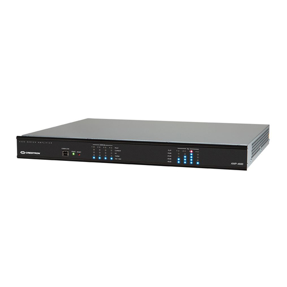
AMP-2800/AMP-4600
Crestron Avia™ Multichannel Commercial Amplifiers
The AMP-2800 and AMP-4600 are high-power, high-efficiency multichannel power amplifiers offering excellent sound quality for use with Crestron
Avia™ DSPs and with Saros® and Vector™ Performance Loudspeakers.
NOTE:
The AMP-2800 and AMP-4600 feature similar operation. For simplicity with this guide, the term "amplifier" is used for both models except
where noted.
Check the Box
Item
AMP-2800 and AMP-4600
Bracket, Rack Ear, 1U (P/N 2032123)
Bracket, Rear Mounting (P/N 2045677)
Cable, Power
Cable, USB 2.0, A - B, 6 ft (1.83 m) (P/N 2014966)
Screw, 4B x 1/4 in., Pan Head, Phillips (P/N 2007195)
AMP-2800 Only
Connector, 2-Pin (P/N 2044402)
Connector, 3-Pin (P/N 2003575)
AMP-4600 Only
Connector, 2-Pin (P/N 2044402)
Connector, 3-Pin (P/N 2003575)
Install the Device
These devices occupy 1U of rack space. To install the included rack ears:
1.
Use a #1 Phillips screwdriver to remove the three screws shown below from each side of the front of the amplifier.
2.
Use a #1 Phillips screwdriver and the included 1/4 in. screws to attach the included rack ears to the front of the amplifier as shown below.
3.
Use a #1 Phillips screwdriver to remove the screws from the rear of the amplifier as shown below, and attach the mounting brackets to the
rear of the amplifier.
Install Front Rack Ears
4.
Mount the device into the rack using eight mounting screws (not included).
Qty
1
2
2
1
1
6
2
2
4
4
Install Rear Mounting Brackets
Connect the Device
Make the necessary connections as called out in the following diagrams. Connect power last.
CAUTIONS:
•
Keep the device unplugged until all of the input, network, and speaker wiring is complete.
•
Check the speaker wires for shorts and frayed wiring around the SPEAKER OUTPUTS connectors.
NOTES:
•
Ensure the unit is properly grounded by connecting the chassis ground lug to an earth ground (building steel).
•
To prevent overheating, do not operate this product in an area that exceeds the environmental temperature range listed in the table of
specifications on the product web page. Fans provide side-to-side airflow for cooling; do not block the ventilation holes.
Hardware Connections, Front, AMP-2800
PWR LED
STATUS LEDs
COMPUTER:
RESET Button
Direct computer connection to device with 6 ft USB cable
Hardware Connections, Front, AMP-4600
PWR LED
STATUS LEDs
COMPUTER:
RESET Button
Direct computer connection to device with 6 ft USB cable
Hardware Connections, Rear, AMP-2800
LINE INPUT 1:
Input
LINE INPUT 2:
From analog source
Attenuator 1
From analog source
Attenuator 2
SPEAKER OUTPUT 1:
SPEAKER OUTPUT 2:
To speaker
To speaker
Hardware Connections, Rear, AMP-4600
LINE INPUTS 1-4 & Input Attenuators:
From analog source
SPEAKER OUTPUTS 1-4:
To speakers
Quick Start
VU Meters
VU Meters
Input
SETUP button
and LED
LAN:
10/100BASE-T Ethernet to LAN
SETUP button
and LED
LAN:
10/100BASE-T Ethernet to LAN
Power Switch
Circuit Breaker
POWER:
Ground
From AC power outlet
Power Switch
Circuit Breaker
POWER:
Ground
From AC power outlet
Advertisement

Related Manuals for Crestron Avia AMP-2800


Summary of Contents for Crestron Avia AMP-2800
- Page 1 AMP-2800/AMP-4600 Crestron Avia™ Multichannel Commercial Amplifiers Connect the Device The AMP-2800 and AMP-4600 are high-power, high-efficiency multichannel power amplifiers offering excellent sound quality for use with Crestron Avia™ DSPs and with Saros® and Vector™ Performance Loudspeakers. NOTE: The AMP-2800 and AMP-4600 feature similar operation. For simplicity with this guide, the term “amplifier” is used for both models except Make the necessary connections as called out in the following diagrams.
- Page 2 Crestron disclaims any proprietary interest in the marks and names of others. Crestron is not responsible for errors in typography or photography CAUTION: Changes or modifications not expressly approved by the manufacturer responsible for compliance could void the user’s authority to operate the equipment.
Need help?
Do you have a question about the Avia AMP-2800 and is the answer not in the manual?
Questions and answers