Advertisement
Quick Links
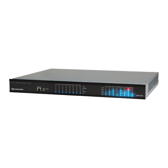
AMP(I)-8075 & AMP(I)-8150
Crestron® 8-Channel Commercial Amplifiers
The Crestron AMP-8075, AMPI-8075, AMP-8150, and AMPI-8150 feature similar operation. For simplicity within this guide, the term "amplifier" is
used for all the models except where noted.
Check the Box
Item
AMP(I)-8075 & AMP(I)-8150
Bracket, Rack Ear, 1U (P/N 2032122)
Bracket, Rear Mounting (P/N 2045677)
Cable, USB 2.0, A - B, 6 ft (1.83 m) (P/N 2014966)
Connector, 2-Pin (P/N 2044402)
Connector, 3-Pin (P/N 2003575)
AMP-8075 and AMP-8150 Only
Fuse, 10.0 A, Time Lag, 1.25 in. x 0.25 in., Ceramic Cartridge, 250 V
(P/N 20177577)
Power Cord, 6 ft 7 in. (2 m) (P/N 2001134)
AMPI-8075 and AMPI-8150 Only
Fuse, 6.3 A, Time Lag, 5 x 20 mm, Ceramic Cartridge, 250 V (P/N 2024846)
Power Cord (P/N varies by country)
Install the Device
These devices occupy 1U of rack space.
To install the included rack ears:
1.
Use a #1 Philips screwdriver to remove the three 1/4 in. screws shown below from each side of the front of the amplifier.
2.
Using the 1/4 in. screws removed in the previous step, attach the included rack ears to the front of the amplifier as shown below.
To install the included rear mounting brackets:
1.
Use a #1 Philips screwdriver to remove the screws from the rear of the amplifier as shown below.
2.
Using the 1/4 in. screws removed in the previous step, attach the mounting brackets to the rear of the amplifier as shown below.
Then, mount the device into the rack using eight mounting screws (not included).
Install Front Rack Ears
Install Rear Mounting Brackets
Connect the Device
Make the necessary connections as called out in the following diagrams. Connect power last.
CAUTIONS:
•
When connecting a Windows® 7 or Windows 8 computer to the COMPUTER port for the first time, make sure the computer has a live
connection to the Internet. For more information, refer to Answer ID 5745 in the Online Help section of the Crestron website
crestron.com).
•
Keep the device unplugged until all of the input, network, and speaker wiring is complete.
•
Check the speaker wires for shorts and frayed wiring around the SPEAKER OUTPUTS connectors.
Qty
2
2
1
8
8
1
1
1
1
(support.
NOTES:
•
Ensure that the unit is properly grounded by connecting the chassis ground lug to an earth ground (building steel).
•
To prevent overheating, do not operate this product in an area that exceeds the environmental temperature range listed in the table of
specifications on the product web page.
Front Panel
PWR LED
STATUS LEDs
RESET Button
Rear Panel
COMPUTER:
Direct Computer Connection to Device
LINE INPUTS 1-8 & Input Attenuators:
From DSP Mixer Outputs
SPEAKER OUTPUTS:
To Speakers
Line Input Connection
If an unbalanced connection to a line input is required, use a jumper between the negative (-) and G (ground) terminals.
Signal
Ground
Jumper
Speaker Connections
The speaker outputs can be wired conventionally, or they can be bridged to deliver higher power to a speaker. Refer to the following diagrams when
connecting speakers.
WARNING:
This amplifier is capable of delivering high power to the loudspeakers. Please use caution and wear adequate hearing protection if
listening at high volume levels, as continued exposure to high sound pressure levels can cause permanent hearing impairment or loss.
Conventional Wiring
Bridged Wiring
1
2
1
Speakers are bridged with the Crestron Avia™ Audio tool, which can be downloaded from www.crestron.com/software. The possible bridging
combinations are Output 1 & Output 2, Output 3 & Output 4, Output 5 & Output 6, and Output 7 and Output 8.
NOTE:
The minimum load impedance for bridged channels is 8 ohms.
VU Meters
LAN:
POWER:
Ethernet to LAN
From AC power source
Power
SETUP button
Ground
and LED
Switch
Advertisement

Related Manuals for Crestron AMP-8075


Summary of Contents for Crestron AMP-8075
- Page 1 When connecting a Windows® 7 or Windows 8 computer to the COMPUTER port for the first time, make sure the computer has a live connection to the Internet. For more information, refer to Answer ID 5745 in the Online Help section of the Crestron website (support.
- Page 2 Underwriters Laboratories, Inc. in the United States and/or other countries. Other trademarks, registered trademarks, and trade names may be used in this document CAN ICES-3 (A)/NMB-3(A) to refer to either the entities claiming the marks and names or their products. Crestron disclaims any proprietary interest in the marks and names of others. Crestron is not responsible for errors in typography or photography.
Need help?
Do you have a question about the AMP-8075 and is the answer not in the manual?
Questions and answers