Table of Contents
Advertisement
Quick Links
Assembly Instructions
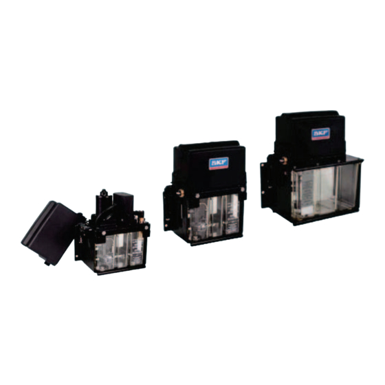
Compact unit for use in centralized
lubrication systems
Product series: KFU2(6)-... and KFUS2-...
Created on:
19.01.2023
Document no.:
951-170-242-EN
Version:
01
Read these instructions before
installation or start-up of the
product and keep them readily
available for later consultation!
Advertisement
Table of Contents

Related Manuals for Lincoln SKF KFU2 Series


Summary of Contents for Lincoln SKF KFU2 Series
- Page 1 Assembly Instructions Compact unit for use in centralized lubrication systems Product series: KFU2(6)-... and KFUS2-... Created on: 19.01.2023 Document no.: 951-170-242-EN Version: Read these instructions before installation or start-up of the product and keep them readily available for later consultation!
- Page 2 Original EC Declaration of Incorporation in accordance with Directive 2006/42/EC, Appendix II Part 1 B The manufacturer hereby declares at its sole responsibility that the partly completed machinery conforms to the essential health and safety requirements of the Machinery Directive 2006/42/EC, Annex I, marked in the Annex to the EC Declaration of Incorporation as applicable and fulfilled at the time of placing on the market.
- Page 3 Appendix to Declaration of Incorporation in accordance with 2006/42/EC, Annex II, No. 1 B Description of the essential health and safety requirements according to 2006/42/EC, Annex I, which have been applied and fulfilled: Table 1 Appendix to Declaration of Incorporation No.: Essential health and safety requirement Applicable:...
-
Page 4: Masthead
SKF (U.K.) Limited, 2 Canada Close, Banbury, Oxfordshire, OX16 2RT, GBR. - North America - SKF Lubrication Business Unit Lincoln Industrial 5148 North Hanley Road, St. Louis, MO. 63134 USA - South America - SKF Argentina Pte. Roca 4145, CP 2001 Rosario, Santa Fe... -
Page 5: Table Of Contents
6.3 Electrical connection .............. 16 Table of contents 6.3.1 Electric motor connection ......... 16 6.3.2 Control unit IG490+924 ........... 17 Masthead ....................4 6.4 Connection of the lubrication line ........18 Table of contents .................. 5 6.5 Laying the lubrication lines ........... 18 Safety alerts, visual presentation, and layout ......... -
Page 6: Safety Alerts, Visual Presentation, And Layout
1. Instruction steps: These indicate a chronological sequence Safety alerts, visual of instruction steps. The numbers of the steps are in bold and are followed by a period. If a new activity follows, the presentation, and layout numbering starts again at “1.” –... -
Page 7: Safety Instructions
1.3 General behaviour when handling the 1. Safety instructions product 1.1 General safety instructions • Familiarize yourself with the functions and operation of the product. The specified assembly and operating steps and their • Putting the products into operation or operating them without sequences must be observed. -
Page 8: Foreseeable Misuse
1.6 Foreseeable misuse NOTE In accordance with the results of the workstation risk Any usage of the product other than as specified in this manual assessment, additional labels (e.g., warnings, safety signs, is strictly prohibited. Particularly prohibited are: prohibition signs, or labels in accordance with CLP/GHS) are •... -
Page 9: Assembly, Maintenance, Fault, Repair
Drill required holes only on non-critical, non-load-bearing 1.18 Assembly, maintenance, fault, parts of the operator's infrastructure. Use existing holes where repair possible. Avoid chafe points. Immobilize any moving or detached parts during the work. Adhere to the specified torques. Prior to the start of this work, all relevant persons must be If guards or safety devices need to be removed, they must be notified of it. - Page 10 Table 2 Residual risks Residual risk Possible in lifecycle Avoidance / Remedy Strong heating of the motor, or motor Switch off the pump. Let parts cool off; remedy the cause. fault, due to jamming. Environmental contamination by K Dispose of contaminated parts according to the applicable lubricants and wetted parts.
-
Page 11: Lubricants
• The lubricant’s ignition temperature has to be at least 2. Lubricants 50 kelvin above the maximum surface temperature of the components. 2.1 General information 2.6 Solid lubricants Lubricants are selected specifically for the relevant application. The manufacturer or operator of the machine should ideally Solid lubricants may only be used after prior consultation with make the selection in consultation with the supplier of the SKF. -
Page 12: Overview, Functional Description
connected via a 4-pin circular connector DIN 72585-A1-4.1- 3. Overview, functional Ag/K1 (only pins 1 and 2 are used, pins 3 and 4 are not used). In both model designs, optional monitoring devices, such as a description float switch, are electrically connected directly via the electrical connection of the monitoring device. -
Page 13: Single-Line Lubrication Systems With Piston Metering Devices
into the storage chamber of the relubrication metering devices. When the electric motor is switched off, the pressure is relieved 3.4.3 Single-line lubrication systems with in the main lubricant line to a residual pressure of ≤ 0.5 bar. In piston metering devices this process, the lubricant is metered within the relubrication metering device and dispensed to the lubrication point via the Single-line systems with piston metering devices generally... -
Page 14: Technical Data
4. Technical data Table 3 Technical data Designation KFU2-40+912/924 KFU6-20+912/924 KFUS2-64+924 KFUS2-60-…+924 General Delivery rate 0.14 l/min 0.14 l/min 0.14 l/min 0.14 l/min Connected load, max. 80 cm 80 cm 80 cm 80 cm Ambient temperature -25 to +75°C -25 to +75°C -25 to +75°C -25 to +75°C Rated capacity of reservoir... -
Page 15: Delivery, Returns, Storage
5.5 Storage conditions for products filled 5. Delivery, returns, storage with lubricant 5.1 Delivery For products filled with lubricant, the permitted storage temperature range is: After receipt of the shipment, it must be inspected for any minimum + 5 °C [+41 °F] shipping damage and for completeness according to the maximum... -
Page 16: Assembly
6. Assembly NOTE 6.1 Setup and attachment Any change to a motorized vehicle, especially the installation of additional equipment such as centralized lubrication systems, must be checked and approved by the WARNING relevant technical authorities in the operator country. Non- Pressure compliance can void the license to operate the vehicle. -
Page 17: Control Unit Ig490+924
Fig. 3 NOTICE Damage due to faulty connection Faulty connection of the compact unit can result in damage • Connect the compact unit according to the connector pin assignment • Observe the local electrical operating conditions and local regulations (e.g., DIN, VDE) •... -
Page 18: Connection Of The Lubrication Line
Fig. 4 NOTICE Damage due to incorrect selection of fittings During assembly, always pay attention to the following: • The fittings used to connect the lubrication line should be rated for the maximum operating pressure of the lubrication unit. • If they are not, the lubrication line system needs to be protected from excessive pressure by means of an overpressure valve. - Page 19 section of the lubrication line from small to large cross-sections in the flow direction of the lubricant. When the cross-section does change, the transition should be gentle. The flow of lubricant in the lubrication lines should not be impeded by sharp bends, angle valves, or flap valves. Unavoidable changes in the cross-section in lubrication lines must have smooth transitions.
-
Page 20: First Start-Up
7. First start-up NOTICE Damage from non-approved lubricant Only lubricants approved for the product may be used. Unsuitable lubricants can lead to failure of the product and to damage. NOTICE Damage from mixing lubricants Different lubricants must not be mixed together. Doing so can cause damage and require extensive cleaning of the product/centralized lubrication system. -
Page 21: Operation
8. Operation The described compact unit works automatically. The lubricant transport in the lubrication lines should, however, be subjected to regular visual inspection. The lubricant fill level in the lubricant reservoir, if present, should likewise be subjected to regular visual inspection. If the lubricant fill level is too low, top up to the maximum mark as described in the "First start-up"... -
Page 22: Maintenance And Repair
9. Maintenance and repair WARNING Pressure Damage and injury from working on pressurized system components Centralized lubrication systems are pressurized during operation. Centralized lubrication systems must therefore be depressurized before starting assembly, maintenance, or repair work, or any system modifications or system repairs. WARNING Electric shock Disconnect the product from the power... -
Page 23: Cleaning
10. Cleaning 10.1 Basics Cleaning should be carried out in accordance with the operator's own company rules, and cleaning agents and devices and the personal protective equipment to be used should likewise be selected in accordance with those rules. Only cleaning agents compatible with the materials may be used for cleaning. -
Page 24: Faults, Causes, And Remedies
11. Faults, causes, and remedies The following table provides an overview of possible malfunctions and their causes. Contact the Service department of SKF Lubrication Systems Germany GmbH if you cannot remedy the malfunction. NOTE Dismantling of the product or individual parts of the product within the statutory warranty period is prohibited and voids any claims. NOTE All assembly, maintenance, and repair work beyond this scope must be performed by the Service department of SKF Lubrication Systems Germany GmbH only. - Page 25 Table 6 Fault analysis and rectification: Malfunction Possible cause Rectification Motor fails to start when the • Operating voltage not applied to the • Check the power supply connection operating voltage is switched on motor • Check the circular connector/power cable and make sure they are connected properly •...
- Page 26 Table 6 Fault analysis and rectification: Malfunction Possible cause Rectification No pressure build up in the main • Air in the main line • Bleed the main line line • Main line leaky or break in line • Repair the main line •...
-
Page 27: Repairs
12. Repairs < WARNING Risk of injury At a minimum, the following safety measures must be taken before any repairs: • Unauthorized persons must be kept away • Mark and secure the work area • Depressurize the product • Isolate the product, and lock and tag it out •... -
Page 28: Appendix
15. Appendix 15.1 China RoHS Table Table 7... - Page 30 skf.com/lubrication ® SKF is a registered trademark of the SKF Group. ™ eLube is a trademark of the SKF Group. © SKF Group 2023 Reprint or reproduction of the contents of this information - even in part - is permitted only with SKF's prior written consent.
Need help?
Do you have a question about the SKF KFU2 Series and is the answer not in the manual?
Questions and answers