Table of Contents
Advertisement
Quick Links
Advertisement
Table of Contents

Subscribe to Our Youtube Channel
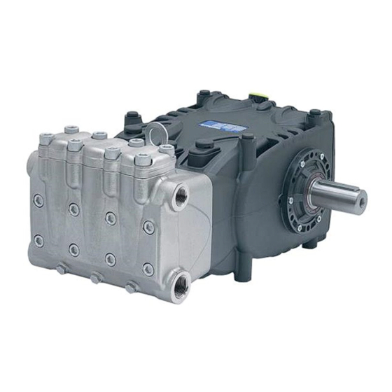
Summary of Contents for Pratissoli HF-WK Series
- Page 1 Serie HF-WK HF18 – HF20 – HF22 – HF25 – HF25N WK355 Manuale uso e manutenzione Use and Maintenance Manual Manuel d'utilisation et d'entretien Betriebs- und Wartungsanleitung Manual de Uso y mantenimiento Manual de uso e manutenção Руководство по эксплуатации и техническому обслуживанию 使用和保养手册...
-
Page 2: Table Of Contents
Contents 1 INTRODUCTION ..................................22 2 DESCRIPTION OF SYMBOLS ..............................22 3 SAFETY ..................................... 22 3.1 General safety warnings .................................. 22 3.2 Essential safety in the high pressure system ..........................22 3.3 Safety during work .................................... 22 3.4 Rules of conduct for the use of lances............................22 3.5 Safety during system maintenance ............................. -
Page 3: Introduction
4. The high pressure pipes must be properly sized for INTRODUCTION maximum operating pressure of the system and always This manual describes the instructions for use and and only used within the operating pressure range maintenance of the HF pump and should be carefully read and speci ed by the Manufacturer of the pipe itself. -
Page 4: Safety During System Maintenance
4. The work area jet range must be absolutely prohibited to PUMP IDENTIFICATION and free from objects that, inadvertently under a pressure Each pump has its own Serial No. XX.XXX.XXX see pos. jet, can be damaged and/or create dangerous situations. an identi cation label, see pos. ... -
Page 5: Dimensions And Weight
DIMENSIONS AND WEIGHT For Standard Version pump dimensions and weight, refer to Fig. 2. For type “A” Flange Version pump dimensions and weight, refer to Fig. 2/a. Fig. 2 Dry weight 60 kg. Fig. 2/a Dry weight 61 kg. Sound emission OPERATING INSTRUCTIONS The sound pressure detection test was performed according The HF pump has been designed to operate to Directive 2000/14 of the European Parliament and Council in environments with atmospheres that are... -
Page 6: Brands And Types Of Oils Recommended
Brands and types of oils recommended The pump is supplied with oil suitable for room temperatures from 0 °C to 30 °C. Some types of recommended oil are indicated in the table below, these oils have additives to increase corrosion resistance and fatigue resistance (DIN 51517 part 2). Alternatively you can also use Automotive Gear SAE 85W-90 oil for gearing lubrication. -
Page 7: Ports And Connections
Viscosity / Room Temperature diagram /s = cSt Ambient temp. (°C) The used oil must be poured unto a suitable container and consigned to an authorised recycling centre. Do not release used oil into the environment under any circumstances. PORTS AND CONNECTIONS PUMP INSTALLATION The HF series pumps (see Fig. 4) are equipped with: Installation... -
Page 8: Rotation Direction
Hydraulic connections Replace the oil lling hole closing service In order to isolate the system from vibrations produced by plug (red) positioned on the rear casing cover. the pump, it is advisable to make the rst section of the duct Check the correct quantity with the oil dipstick. -
Page 9: Filtration
Filtration 1 lter must be installed on the pump suction line, positioned as indicated in Fig. 6 and Fig. 6/a. With a manually activated control valve 1 Filter 1 Inlet 2 Plunger pump 3 Pressure gauge Supply tank 4 Safety valve 5 Manual control valve Bypass Fig. 6 With pneumatic control valve... -
Page 10: V-Belt Transmission
The graph does not take into account pipe Outlet duct With a ow rate of ~ 74 l/min and a water velocity of 5.5 m/sec. resistance, valves, load loss produced by the length The graph line joining the two scales meets the central scale of the ducts, the viscosity of the liquid pumped or showing the diameters, corresponding to a value of ~ 19 mm. -
Page 11: Transmission De Nition
9.11 Transmission de nition To prevent irregular radial loads on the shaft and the relative bearing, follow these directions: a) Use pulleys with V-belts with the size of the groove required/recommended by the manufacturer of belt used. In the absence of directions, follow Fig. 8 and the table in Fig. 9. -
Page 12: De Nition Of Static Pull To Apply On Belts
b) Use high performance belts – for example XPB instead of SPB – as a lower quantity of belts for the same transmitted power may be necessary and a consequent shorter resulting distance compared to the shaft shoulder (P.T.O) “a” of Fig. 10. Shaft shoulder (P.T.O.) -
Page 13: Start-Up And Operation
Transmission can be carried out: 5. Oil in the pump casing is at level, veri ed with a dipstick (Fig. 14, pos. ) and exceptionally with a level indicator (Fig. 14, pos. ). By means of the V-Belts, withdrawable Max Torque is: 65 Nm which corresponds to: 7 HP at 750 rpm;... -
Page 14: Method For Lling Pump With Anti-Corrosion Emulsion Or Anti-Freeze Solution
12.2 Method for lling pump with anti-corrosion OPERATING FAULTS AND THEIR emulsion or anti-freeze solution POSSIBLE CAUSES Method for lling pump with anti-corrosion emulsion or The pump does not produce any noise upon anti-freeze solution using an external diaphragm pump based start-up: on the layout shown in par. 9.7, between pos. -
Page 15: Exploded Drawing And Parts List
EXPLODED DRAWING AND PARTS LIST... -
Page 19: Flushing Circuit Diagram Of Use
FLUSHING CIRCUIT DIAGRAM OF USE Adhere to the following values for proper system operation: minimum circuit ow rate 4 l/min, maximum uid pressure 6 bar. Pump head Pump casing... -
Page 20: Declaration Of Incorporation
DECLARATION OF INCORPORATION DECLARATION OF INCORPORATION (In accordance with Annex II of European Directive 2006/42/EC) The manufacturer INTERPUMP GROUP S.p.A. - Via E. Fermi, 25 - 42049 - S. ILARIO D’ENZA (RE) - Italy DECLARES that the product identi ed and described as follows: Designation: Pump Type:...


Need help?
Do you have a question about the HF-WK Series and is the answer not in the manual?
Questions and answers