
Related Manuals for Pratissoli INTERPUMP KT Series


Summary of Contents for Pratissoli INTERPUMP KT Series
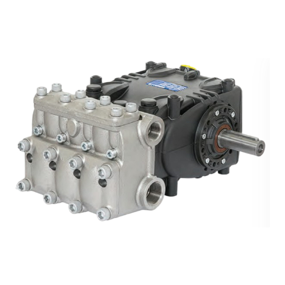
- Page 1 Serie KT-KTB-WK-W KT24 - KT26 - KT28 -KT30 - KT32 - KT34 - KT36- KT40 - KT36B - KT40B - WK155 - WK6 - WK8 - W120120 - W100140 Use and Maintenance Manual...
-
Page 2: Table Of Contents
Contents 1 INTRODUCTION ..................................22 2 DESCRIPTION OF SYMBOLS ..............................22 3 SAFETY ..................................... 22 3.1 General safety warnings .................................. 22 3.2 Essential safety in the high pressure system ..........................22 3.3 Safety during work .................................... 22 3.4 Rules of conduct for the use of lances............................22 3.5 Safety during system maintenance ............................. -
Page 3: Introduction
INTRODUCTION Essential safety in the high pressure system 1. The pressure line must always be provided with a safety This manual describes the instructions for use and valve. maintenance of the KT-KTB-W-WK LOW-PRESSURE version 2. High pressure system components, particularly for systems pump and should be carefully read and understood before that operate primarily outside, must be adequately using the pump. -
Page 4: Safety During System Maintenance
2. The operator must always wear a helmet with a protective PUMP IDENTIFICATION visor, waterproof gear and wear boots that are appropriate Each pump has its own Serial No. XX.XXX.XXX see pos. for use and can ensure a good grip on wet oors. an identi cation plate see pos. -
Page 5: Technical Characteristics
TECHNICAL CHARACTERISTICS Flow rate Pressure Power Model l/min 1450 51.1 13.50 3625 24.4 33.2 KT 24 1750 61.7 16.30 2900 23.6 32.1 KT 26 1450 60.0 15.85 3625 28.7 39.0 1450 69.6 18.40 2900 26.6 36.2 KT 28 1750 84.0 22.20 2538 28.0... -
Page 6: Operating Instructions
OPERATING INSTRUCTIONS Manufacturer Lubricant Falcon CL220 The KT-KTB-W-WK LOW-PRESSURE version pumps have been designed to operate in environments with atmospheres that are not potentially explosive, with ltered water (see par. 9.7) and at a maximum ELF POLYTELIS 220 temperature of 40 °C. REDUCTELF SP 220 Other liquids can be used only upon formal approval by the Engineering Department or Customer... -
Page 7: Ports And Connections
In any case the oil must be changed at least once a year, as it is degraded by oxidation. For a room temperature other than between 0 °C - 30 °C, follow the instructions in the following diagram, considering that oil must have a minimum viscosity of 180 cSt. Viscosity / Room Temperature diagram /s = cSt Ambient temp. -
Page 8: Pump Installation
PUMP INSTALLATION In all cases the transmission must be assembled correctly to avoid incorrect or harsh operation of Installation the connection parts and to prevent excessive The pump must be xed horizontally using the M12x1.5 wear, temperature rise and/or hazardous breakages threaded support feet. -
Page 9: Hydraulic Connections
2. The layout must be such as to prevent cavitation Hydraulic connections problems. In order to isolate the system from vibrations produced by 3. Completely airtight and constructed to ensure a perfectly the pump, it is advisable to make the rst section of the duct hermetic seal through time. -
Page 10: Outlet Line
The lter, which is to be installed as close to the pump as Optimal speeds: possible, must be easily inspectable and have the following Suction: ≤ 0.5 m/sec. speci cations: Outlet: ≤ 5.5 m/sec. 1. Minimum ow rate at least 3 times the nominal ow rate of the pump. -
Page 11: Transmission De Nition
Fig. 7 9.11 Transmission de nition To prevent irregular radial loads on the shaft and the relative bearing, follow these directions: a) Use pulleys with V-belts with the size of the groove required/recommended by the manufacturer of belt used. In the absence of directions, follow Fig. 8 and the table in Fig. 9. - Page 12 Dimensions (in mm) Belt section as per DIN symbol XPB/SPB XPC/SPC DIN 7753 part 1 and B.S. 3790 symbol B.S./ISO Belt section as per DIN symbol DIN 2215 and B.S. 3790 symbol B.S./ISO Pitch width 14.0 19.0 α = 34° 18.9 26.3 Increased grooving width b...
-
Page 13: De Nition Of Static Pull To Apply On Belts
. Unless otherwise stated by the supplier of the belts, Note 9.12 De nition of static pull to apply on belts control of proper pull and its relative re-tensioning should be Static pull depends on: performed after no less than 30 minutes of motion necessary a) The wheelbase between the two pulleys (belt length). -
Page 14: Start-Up
4. The coupling tolerances on the pump/transmission axis PUMP STORAGE (half-joint misalignment, Cardan joint tilt, belt pulling, 12.1 Long-term inactivity etc.) remain within limits required by the transmission If the pump is started for the rst time after a long manufacturer. -
Page 15: Warranty Conditions
The pressure supplied by the pump is insu cient: WARRANTY CONDITIONS The user ow (nozzle) is or has become greater The guarantee period and conditions are contained in the than the pump capacity. purchase agreement. Insu cient revolutions per minute. The guarantee will in any case be invalidated if: Excessive leakage from the pressure seals. -
Page 16: Exploded Drawing And Parts List
EXPLODED DRAWING AND PARTS LIST... -
Page 19: Flushing Circuit Diagram Of Use
FLUSHING CIRCUIT DIAGRAM OF USE Adhere to the following values for proper system operation: minimum circuit ow rate 4 l/min, maximum uid pressure 6 bar Pump head Pump casing... -
Page 20: Declaration Of Incorporation
DECLARATION OF INCORPORATION DECLARATION OF INCORPORATION (In accordance with Annex II of European Directive 2006/42/EC) The manufacturer INTERPUMP GROUP S.p.A. - Via E. Fermi, 25 - 42049 - S. ILARIO D’ENZA - Italy DECLARES that the product identi ed and described as follows: Designation: Pump Type:...
Need help?
Do you have a question about the INTERPUMP KT Series and is the answer not in the manual?
Questions and answers