Table of Contents
Advertisement
Advertisement
Table of Contents

Related Manuals for Pratissoli KF Series


Summary of Contents for Pratissoli KF Series
- Page 1 Serie KF KF - KFR Manuale uso e manutenzione Use and Maintenance Manual Manuel d’utilisation et d’entretien Betriebs- und Wartungsanleitung Manual de Uso y mantenimiento Manual de uso e manutenção Руководство по эксплуатации и техническому обслуживанию 使用和保养手册 Kullanma ve bakım kılavuzu...
-
Page 2: Table Of Contents
Contents 1 INTRODUCTION ..................................23 2 DESCRIPTION OF SYMBOLS ..............................23 3 SAFETY ..................................... 23 3.1 General safety warnings .................................. 23 3.2 Essential safety in the high pressure system ..........................23 3.3 Safety during work .................................... 23 3.4 Rules of conduct for the use of lances............................23 3.5 Safety during system maintenance ............................. -
Page 3: Introduction
INTRODUCTION Essential safety in the high pressure system 1. The pressure line must always be provided with a safety This manual describes the instructions for use and valve. maintenance of the KF pump and should be carefully read and 2. High pressure system components, particularly for systems understood before using the pump. -
Page 4: Safety During System Maintenance
2. The operator must always wear a helmet with a protective PUMP IDENTIFICATION visor, waterproof gear and wear boots that are appropriate Each pump has its own Serial No. XX.XXX.XXX see point for use and can ensure a good grip on wet oors. an identi cation plate see point ... -
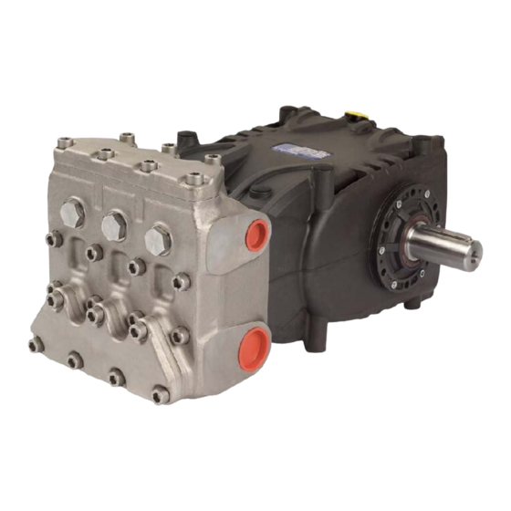
Page 5: Dimensions And Weight
DIMENSIONS AND WEIGHT For Standard Version pump dimensions and weight, refer to Fig. 2. Fig. 2 Dry weight 68 kg. Brands and types of oils recommended OPERATING INSTRUCTIONS The pump is supplied with oil suitable for room temperatures The KF pump has been designed to operate in from 0 °C to 30 °C. - Page 6 Manufacturer Lubricant Wintershall Ersolon 220 Wintershall Wiolan CN 220 RANDO HD 220 TOTAL Cortis 220 Check the oil level and top up if necessary Using the oil dipstick pos. , Fig. 3. The correct checking of the oil level is made with the pump not running, at room temperature.
-
Page 7: Ports And Connections
PORTS AND CONNECTIONS The KF series pumps (see Fig. 4) are equipped with: No. 2 “IN“ inlet ports 1” Gas. Line connection to any of the two ports is indi erent for proper pump functioning. The unused ports must be hermetically closed. -
Page 8: Version Change
Version change Suction line The pump version is de ned as right when: For smooth operation of the pump, the suction line must have Observing the pump facing the head side, the pump shaft the following characteristics: must have a PTO shank on the right side. 1. -
Page 9: Outlet Line
With pneumatic control valve 1 Filter 1 Inlet 2 Plunger pump 3 Pressure gauge Supply tank 4 Safety valve 5 Pneumatic control valve Bypass Fig. 6/a The lter, which is to be installed as close to the pump as Outlet duct possible, must be easily inspectable and have the following With a ow rate of ~ 170 l/min and a water velocity of speci cations:... -
Page 10: Transmission De Nition
The radial load on the shaft must not exceed 7500 N For dimensions di ering from those speci ed (value necessary for Layout de nition). The transmission is above, contact our Technical or Customer Service considered adequate if the load is applied at a maximum Departments. - Page 11 Dimensions (in mm) Belt section as per DIN symbol XPB/SPB XPC/SPC DIN 7753 part 1 and B.S. 3790 symbol B.S./ISO Belt section as per DIN symbol DIN 2215 and B.S. 3790 symbol B.S./ISO Pitch width 14.0 19.0 α = 34° 18.9 26.3 Increased grooving width b...
-
Page 12: De Nition Of Static Pull To Apply On Belts
Transmission of power from the second PTO Values of the static pull to be applied can be obtained from Upon request, KF series pumps can be supplied with an the diagram in Fig. 11 for belts with a XPB pro le in relation to auxiliary PTO on the opposite side to the drive (Transmission the wheelbase. -
Page 13: Start-Up And Operation
START-UP AND OPERATION PREVENTIVE MAINTENANCE For pump reliability and e ciency, comply with maintenance 10.1 Preliminary checks intervals as shown in the table of Fig. 15. Before start-up, ensure that: The suction line is connected and pressurized PREVENTIVE MAINTENANCE (see par. 9.4 - 9.5 - 9.6) the pump must never Every 500 hours Every 1000 hours run dry. -
Page 14: Precautions Against Frost
PRECAUTIONS AGAINST FROST The pump does not supply the nominal ow rate/ excessive noise: Follow the instructions in Chapter 12 in areas and Insu cient supply (see various causes as above). times of the year at risk of frost (see par. 12.2). Pump speed is below the rated speed. -
Page 15: Exploded Drawing And Parts List
EXPLODED DRAWING AND PARTS LIST... -
Page 17: Flushing Circuit Diagram Of Use
FLUSHING CIRCUIT DIAGRAM OF USE Adhere to the following values for proper system operation: minimum circuit ow rate 4 l/min, maximum uid pressure 6 bar Pump casing Pump head... -
Page 18: Special Versions
SPECIAL VERSIONS 18.1.2 Water temperature The maximum permissible water temperature The KF pump is also available in the special version: is 40 °C. However, the pump can be used with • water up to a temperature of 60 °C, but only for The following information is helpful in deciding how to short periods. -
Page 19: Exploded View
18.1.7 Exploded view... -
Page 21: Declaration Of Incorporation
DECLARATION OF INCORPORATION DECLARATION OF INCORPORATION (In accordance with Annex II of European Directive 2006/42/EC) The manufacturer INTERPUMP GROUP S.p.A. - Via E. Fermi, 25 - 42049 - S. ILARIO D’ENZA - Italy DECLARES that the product identi ed and described as follows: Designation: Pump Type:...
Need help?
Do you have a question about the KF Series and is the answer not in the manual?
Questions and answers