
Related Manuals for Pratissoli MW Series


Summary of Contents for Pratissoli MW Series
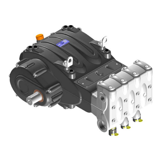
- Page 1 Menu MW Series MW32 – MW36 – MW40 MW45 – MW50 – MW55 Use and maintenance manual...
-
Page 2: Table Of Contents
INDEX 1. INTRODUCTION 2. DESCRIPTION OF SYMBOLS 3. SAFETY 3.1 General safety warnings.......................4 3.2 Essential safety in the high pressure system ................4 3.3 Safety during work.......................4 3.4 Rules of conduct for the use of lances .................4 ... -
Page 3: Introduction
1. INTRODUCTION This manual describes the instructions for use and maintenance of the MW pump and should be carefully read and understood before using the pump. Proper pump operation and duration depend on the correct use and maintenance. Interpump Group disclaims any responsibility for damage caused by negligence or failure to observe with the standards described in this manual. -
Page 4: Safety
3. SAFETY 3.1 General safety warnings Improper use of pumps and high pressure systems as well as non-compliance with installation and maintenance standards can cause serious damage to people and/or property. Anyone assembling or using high pressure systems must possess the necessary competence to do so, knowing the characteristics of the components that will assemble/use and take all precautions necessary to ensure maximum safety in all operating conditions. -
Page 5: Safety During System Maintenance
Note: appropriate clothing will protect against sprays of water but not from direct impact with jets of water or very close sprays. Additional protections may therefore be necessary in certain circumstances. 3. It is generally best to organise personnel into teams of at least two people capable of giving mutual and immediate assistance in case of necessity and of taking turns during long and demanding operations. -
Page 6: Technical Characteristics
5. TECHNICAL CHARACTERISTICS Flow rate Pressure Power Model Rpm/1’ l/min 1500 35.7 4350 MW 32 1800 35.9 4350 2200 136.5 36.1 4350 1500 45.2 3480 MW 36 1800 45.4 3480 2200 45.7 3480 1500 55.7 2755 MW 40 1800 56.0 2755 2200 56.3... -
Page 7: Dimensions And Weight
6. DIMENSIONS AND WEIGHT For dimensions and weights of MW32, MW36 and MW40 pumps, refer to fig. 2. Dry weight - 244 Kg fig. 2 For dimensions and weights of MW45, MW50 and MW55 pumps, refer to fig. 2/a. Dry weight – 245 Kg fig. -
Page 8: Operating Instructions
7. OPERATING INSTRUCTIONS The MW pump was designed to work with clean water (see point 9.7) and at maximum temperature of 40°C. Other liquids can be used only after approval by the Technical or Customer Service Departments. 7.1 Water temperature The maximum permissible water temperature is 40°C. -
Page 9: Brands And Types Of Oils Recommended
7.4 Brands and types of oils recommended The pump is supplied with oil suitable for room temperatures from 0°C to 30°C. Some types of recommended oil are indicated in the table below. These oils have additives to increase corrosion resistance and fatigue resistance (DIN 51517 part 2). Alternatively you can also use Automotive SAE 85W-90 oil for gearing lubrication. - Page 10 In any case the oil must be changed at least once a year, as it is degraded by oxidation. For a room temperature other than between 0°C - 30°C, follow the instructions in the following diagram, considering that oil must have a minimum viscosity of 180 cSt. Viscosity / Room temperature Diagram Room Temp.
-
Page 11: Ports And Connections
8. PORTS AND CONNECTIONS The MW series pumps are equipped with (see fig.4 and fig.4/a): 2 “IN“ inlet ports: G2” (in versions MW32, MW36, MW40) Ø66 mm (in versions MW45, MW50, MW55) Line connection to any of the two ports is indifferent for proper pump functioning. -
Page 12: Pump Installation
9. PUMP INSTALLATION 9.1 Installation The pump must be fixed horizontally using the M16 threaded support feet. Tighten the screws with a torque of 200 Nm. The base must be perfectly flat and rigid enough as not to allow bending or misalignment on the pump coupling axis/transmission due to torque transmitted during operation. -
Page 13: Rotation Direction
9.2 Rotation direction The PTO rotation direction is indicated by an arrow located on the reduction gear cover. From a position facing the pump head, the rotation direction will be as in fig. 5 fig. 5 9.3 Version change and reduction gear positioning The pump version is defined as right when: Observing the pump facing the head side, the pump shaft must have a PTO shank on the right side. -
Page 14: Hydraulic Connections
LEFT SIDE RIGHT SIDE fig. 6 The reduction gear position can only be modified by trained and authorised personnel carefully following directions contained in the repair manual. 9.4 Hydraulic connections In order to isolate the system from vibrations produced by the pump, it is advisable to make the first section of the duct adjacent to the pump (both suction and outlet) with flexible piping. -
Page 15: Suction Line
9.6 Suction line For a smooth operation of the pump, the suction line should have the following characteristics: 1. Minimum internal diameter as indicated in the graph at point 9.9 and equal to or exceeding that of the pump head. Localised restrictions should be avoided along the run of the duct, as these can cause load losses resulting in cavitation. -
Page 16: Outlet Line
With a pneumatically activated control valve 1 Filter n.1 6 Plunger pump 2 Booster Pump 7 Pressure gauge 3 Filter n.2 8 Safety valve 9 Accumulator 4 Pressure gauge 10 Pneumatic control valve 5 Pressure regulator Inlet Prefilter Bypass Supply Tank fig. -
Page 17: Calculation Of The Internal Diameter Of The Duct Pipes
9.9 Calculation of the internal diameter of the duct pipes. To determine the internal diameter of the duct, refer to the following diagram: Suction duct With a flow rate of ~ 400 L/min and a water velocity of 1 m/sec. The graph line joining the two scales meets the central scale showing the diameters, corresponding to a value of ~ 90 mm. -
Page 18: V-Belt Transmission
9.10 V-belt transmission As indicated in point 9.1, the pump can be controlled by a v-belt system only in exceptional cases. For proper layout sizing, consult our Technical or Customer Service Departments. 10. START-UP AND OPERATION 10.1 Preliminary checks Before start-up, ensure that: The suction line is connected and pressurised (see chapter 9): the pump must never run dry. -
Page 19: Start-Up
10.2 Start-up 1. At first start-up, verify that the rotation direction is correct. 2. Check proper pump supply. 3. Start-up the pump without any load. 4. Check that the rotation rpm during operation does not exceed the nominal rpm of the pump. 5. -
Page 20: Pump Storage
12. PUMP STORAGE 12.1 Method for filling pump with anti-corrosion emulsion or anti-freeze solution using an external diaphragm pump based on the layout shown in point 9.7 a) Close the filter drainage, if open. b) Make sure the connecting pipe is clean, spread with grease and connect them to the high pressure discharge. -
Page 21: Operating Faults And Their Possible Causes
15. OPERATING FAULTS AND THEIR POSSIBLE CAUSES The pump does not produce any noise upon start-up: The pump is not primed and is running dry. No suction water. Valves are blocked. The outlet line during is closed and does not allow air present in the pump head to come out. -
Page 22: Exploded Drawing And Parts List
16. EXPLODED DRAWING AND PARTS LIST MW H.P. DIS.COD.73.9500.00... - Page 23 DIS.COD.73.9501.00 MW L.P.
- Page 24 MWN H.P. DIS.COD.73.9502.00...
- Page 25 MWN L.P. DIS.COD.73.9503.00...
- Page 26 Violators will be prosecuted according to law with appropriate legal action. PRATISSOLI a brand of INTERPUMP GROUP S.P.A. 42049 S.ILARIO - REGGIO EMILIA ( ITALY) Tel. +39 - 0522 - 904311 Fax +39 - 0522 - 904444 E-mail: info@pratissolipompe.com...
Need help?
Do you have a question about the MW Series and is the answer not in the manual?
Questions and answers