Sign In
Upload
Manuals
Brands
SKF Manuals
Water Pump
MKF Series
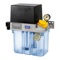
SKF MKF Series Lubrication Pump Unit Manuals
Manuals and User Guides for SKF MKF Series Lubrication Pump Unit. We have
2
SKF MKF Series Lubrication Pump Unit manuals available for free PDF download: Manual, Assembly Instructions Manual
SKF MKF Series Manual (102 pages)
Brand:
SKF
| Category:
Water Pump
| Size: 2 MB
Table of Contents
EC Declaration of Incorporation
2
Table of Contents
4
Explanation of Symbols and Signs
7
Safety Instructions
9
General Safety Instructions
9
General Behavior When Handling the Product
9
Qualiied Technical Personnel
10
Electric Shock Hazard
11
System Pressure or Hydraulic Pressure Hazard
11
Operation
11
Assembly/Maintenance/Malfunction/Decommissioning/Disposal
12
Intended Use
12
Foreseeable Misuse
13
Disclaimer of Liability
13
Referenced Documents
14
Warning Labels on the Product
14
Residual Risks
15
Lubricants
17
General Information
17
Selection of Lubricants
17
Approved Lubricants
18
Lubricants and the Environment
19
Lubricant Hazards
19
Overview
20
Description of Designs
20
Equipment of a Mkx Gear Pump Unit
21
Order Code
22
MKU Gear Pump Units
22
MKF Gear Pump Units
24
MKL Gear Pump Units
26
Assembly
27
General Information
27
Setup and Attachment
27
Minimum Mounting Dimensions
28
Assembly Drawing with Minimum Installation Dimensions
29
MKU/MKF Gear Pump Units with
29
MKU/MKF/MKL Gear Pump Units with 3-Liter Plastic Reservoir for Oil and Luid Grease
30
MKU/MKF/MKL Gear Pump Units with 3-Liter Metal Reservoir for Oil and Luid Grease
31
MKU/MKF/MKL Gear Pump Units with 6-Liter Plastic Reservoir for Oil and Luid Grease
32
Example Hydraulic Connection
33
Example MKF
33
Example Hydraulic Connection MKU
34
Example Hydraulic Connection MKL
35
Attachment of a Gear Pump Unit
36
Electrical Connection
37
Electric Motor Connection
37
Electric Motor Connection with Cable Socket and Circular Plug
38
Electric Motor Connection with Cable Glands
39
Terminal Diagrams
40
Legend to the Terminal Diagrams
40
MKU, 2-Liter Reservoir
41
MKF, 2-Liter Reservoir
45
MKU, 3- or 6-Liter Reservoir
49
Voltage Design 230/115 VAC
57
Terminal Diagrams for
57
IGZ36 Control Unit, Voltage Design 230/115 VAC
60
IGZ36 Control Unit, Voltage Design 24 VDC
60
IG54 Control Unit, Voltage Design 230/115 VAC
61
IG54 Control Unit, Voltage Design 24 VDC
61
Technical Connection Data
62
Lubrication Line Connection
63
Assembly of the Main Lubrication Line with Tapered Sleeve Union
64
Assembly of the Lubrication Lines Using Plug Connectors
65
System Criteria for MKL Gear Pump Unit
66
General Information on Lubrication Line Arrangement
67
Venting Centralized Lubrication System
68
Note on the Rating Plate
69
Notes on the CE Marking
69
Safety Instructions
72
Lubricants
72
Delivery, Returns, and Storage
73
Checking the Delivery
73
Returns
73
Storage
73
Lubrication Units
73
Electronic and Electrical Devices
73
General Notes
73
Assembly
74
Information on Assembly
74
Functional Description
74
Structure of a Gear Pump Unit
75
Gear Pump Unit Without Control Unit
77
Gear Pump Unit with Control Unit (IG/IZ38, IGZ36, IG54)
78
Control Unit Designs with Their Basic Settings
79
Lubrication Systems
81
General
81
Total-Loss Lubrication Systems
81
Single-Line Systems with Piston Distributors
81
Lubricating Cycle Sequence
82
Lubricating Cycle of Prelubrication
82
Distributor
82
Lubricating Cycle of Relubrication Distributor
83
Commissioning
84
General
84
Interim Lubrication Pushbutton
84
Commissioning
85
Operation/Shutdown and Disposal
86
Operation
86
Temporary Shutdown
86
Recommissioning
87
Shutdown and Disposal
87
Maintenance
88
General
88
Maintenance Schedule
89
Service
89
Malfunctions, Causes, and Remedies
90
Prior to Beginning Troubleshooting
90
Replacing a Defective Fuse (24 VDC)
91
Commissioning, Product, and System Malfunctions
92
Technical Data
95
Spare Parts
96
Accessories
99
Advertisement
SKF MKF Series Assembly Instructions Manual (68 pages)
Brand:
SKF
| Category:
Water Pump
| Size: 5 MB
Table of Contents
Masthead
4
Table of Contents
5
Safety Alerts, Visual Presentation, and Layout
7
Safety Instructions
8
General Safety Instructions
8
General Electrical Safety Instructions
8
General Behaviour When Handling the Product
8
Intended Use
8
Persons Authorized to Use the Product
8
Foreseeable Misuse
9
Referenced Documents
9
Prohibition of Certain Activities
9
Painting Plastic Components and Seals
9
Safety Markings on the Product
9
Note on the Type Plate
9
Notes on CE Marking
9
Note on Low Voltage Directive
10
Note on UKCA Marking
10
Note on EAC Marking
10
Note on China Rohs Mark
10
Emergency Shutdown
10
Assembly, Maintenance, Fault, Repair
10
First Start-Up, Daily Start-Up
10
Residual Risks
11
Lubricants
12
General Information
12
Material Compatibility
12
Temperature Properties
12
Aging of Lubricants
12
Avoidance of Faults and Hazards
12
Solid Lubricants
12
Overview, Functional Description
13
General
13
Structure of a Gear Pump Unit
13
Description of Designs
14
Gear Pump Unit Without Control Unit
15
Gear Pump Unit with Control Unit (IG/IZ38, IGZ36, IG54)
15
Control Unit Designs with Their Basic Settings
15
Lubrication Systems
17
General
17
Total-Loss Lubrication Systems
17
Single-Line Lubrication Systems with Piston Metering Devices
18
Lubrication Cycle Sequence
18
Lubrication Cycle of Relubrication Metering Device
18
Technical Data
19
Technical Connection Data
19
Order Code for MKU Gear Pump Units
20
Order Code for MKF Gear Pump Units
22
Order Code for MKL Gear Pump Units
23
Delivery, Returns, Storage
24
Delivery
24
Return Shipment
24
Storage
24
Storage Temperature Range
24
Storage Conditions for Products Filled with Lubricant
24
Storage Period up to 6 Months
24
Storage Period between 6 and 18 Months
24
Storage Period more than 18 Months
24
Assembly
25
General
25
Setup and Attachment
25
Minimum Mounting Dimensions
25
Assembly Drawing with Minimum Mounting Dimensions
26
MKU/MKF Gear Pump Units with 2-Liter Plastic Reservoir for Oil and Fluid Grease
26
MKU/MKF/MKL Gear Pump Units with 3-Liter Plastic Reservoir for Oil and Fluid Grease
27
MKU/MKF/MKL Gear Pump Units with 3-Liter Metal Reservoir for Oil and Fluid Grease
28
MKU/MKF/MKL Gear Pump Units with 6-Liter Plastic Reservoir for Oil and Fluid Grease
29
Connection Examples
30
MKF Hydraulic Connection
30
MKU Hydraulic Connection
30
MKL Hydraulic Connection
31
Attachment of a Gear Pump Unit
31
Electrical Connection
31
Electric Motor Connection
32
Electric Motor Connection with Cable Socket and Circular Connector
33
Electric Motor Connection with Screwed Glands
33
Terminal Diagrams
33
Legend to the Terminal Diagrams
33
Terminal Diagrams for MKU/MKF, Without Control Unit
34
Terminal Diagrams for MKU/MKF/MKL, 3- or 6-Liter Reservoir, with Control Unit
46
MKF, IG/IZ38 Control Unit, Voltage Design 230/115 VAC
47
Lubrication Line Connection
49
Assembly of the Main Lubrication Line with Cone Ring Fitting
50
Assembly of the Lubrication Lines Using Quick Couplings50
50
System Criteria for MKL Gear Pump Unit
51
General Information on Lubrication Line Routing
51
Venting an MKU/MKF/MKL Centralized Lubrication System
52
First Start-Up
53
Operation
54
General
54
Intermediate Lubrication Pushbutton
54
Maintenance and Repair
55
General
55
Maintenance Schedule
55
Service
55
Cleaning
56
Basics
56
Interior Cleaning
56
Exterior Cleaning
56
Faults, Causes, and Remedies
57
Prior to Beginning Troubleshooting
57
Replacing a Defective Fuse (24 VDC)
57
Commissioning, Product, and System Malfunctions
58
Repairs
60
Shutdown, Disposal
60
Temporary Shutdown
60
Permanent Shutdown, Disassembly
60
Disposal
60
Spare Parts
61
Accessories
63
Appendix
67
China Rohs Table
67
Advertisement
Related Products
SKF MKU Series
SKF MKL Series
SKF MPB Series
SKF SKF-MPB-PUMP-1 Series
SKF MAX-1-2-115-IF105-R-V2
SKF MAX-2-2-115-IF105-R-V2
SKF MAX-1-1-230-IF105-U-V2
SKF MAX-1-1-115-IF105-R-V2
SKF M 2
SKF MF 1
SKF Categories
Water Pump
Lubrication systems
Measuring Instruments
Tools
Industrial Equipment
More SKF Manuals
Login
Sign In
OR
Sign in with Facebook
Sign in with Google
Upload manual
Upload from disk
Upload from URL