
Related Manuals for Supero SAS 822TQ BACKPLANE


Summary of Contents for Supero SAS 822TQ BACKPLANE
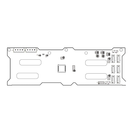
- Page 1 JP13 JP10 JP37 JP36 JP43 JP45 JP34 JP33 JP18 JP41 JP40 JP42 JP46 JP38 JP29 JP50 JP26 JP44 SAS 822TQ BACKPLANE USER'S GUIDE Rev. 1.0b...
- Page 2 Backplane User's Guide The information in this User’s Manual has been carefully reviewed and is believed to be accurate. The vendor assumes no responsibility for any inaccuracies that may be contained in this document, makes no commitment to update or to keep current the information in this manual, or to notify any Please Note: For the most up-to-date version of person or organization of the updates.
-
Page 3: Table Of Contents
Safety Information and Technical Specifi cations Table of Contents Chapter 1: Safety Guidelines 1-1 ESD Safety Guidelines ..................1-1 1-2 General Safety Guidelines .................. 1-1 1-3 An Important Note to Users ................1-1 Chapter 2: Jumper Settings and Pin Defi nitions 2-1 Front Connectors and Jumpers ................ - Page 4 Backplane User's Guide Contacting SuperMicro Headquarters Address: SuperMicro Computer, Inc. 980 Rock Ave. San Jose, CA 95131 U.S.A. Tel: +1 (408) 503-8000 Fax: +1 (408) 503-8008 Email: marketing@supermicro.com (General Information) support@supermicro.com (Technical Support) Web Site: www.supermicro.com Europe Address: SuperMicro Computer B.V. Het Sterrenbeeld 28, 5215 ML 's-Hertogenbosch, The Netherlands Tel:...
-
Page 5: Chapter 1: Safety Guidelines
Safety Information and Technical Specifi cations Chapter Safety Guidelines To avoid personal injury and property damage, carefully follow all the safety steps listed below when accessing your system or handling the components. ESD Safety Guidelines Electric Static Discharge (ESD) can damage electronic com ponents. To prevent dam- age to your system, it is important to handle it very carefully. - Page 6 Backplane User's Guide Notes...
-
Page 7: 2-1 Front Connectors And Jumpers
Safety Information and Technical Specifi cations Chapter 2: Jumper Settings and Pin Defi nitions 2-1 Front Connectors and Jumpers JP13 JP10 JP37 JP36 JP43 JP45 JP34 JP33 JP18 JP41 JP40 JP42 JP46 JP38 JP29 JP50 JP38 JP26 JP44 JP37 JP36 JP43 JP45 JP34... -
Page 8: Front Connector Pin Defi Nitions
Backplane User's Guide Front Connector and Pin Defi nitions #1. Backplane Main Power Connectors Backplane Main Power The 4-pin connectors, designated JP10, and 4-Pin Connector (JP10 and JP13) JP13, provide power to the backplane. See Pin# Defi nition the table on the right for pin defi nitions. +12V 2 and 3 Ground... - Page 9 Safety Information and Technical Specifi cations #5/#6 I C Connectors C Connector Pin Defi nitions The I C Connectors, designated JP44 and (JP44 and JP45) JP45 are used to monitor HDD activity and Pin# Defi nition status. See the table on the right for pin Data defi...
-
Page 10: Front Jumper Locations And Pin Defi Nitions
Backplane User's Guide Front Jumper Locations and Pin Defi nitions JP18 JP29 JP13 JP10 JP37 JP36 JP43 JP45 JP34 JP33 JP18 JP41 JP40 JP42 JP46 JP38 JP29 JP50 JP26 JP44 JP37 JP36 JP43 JP34 JP33 JP41 JP40 JP42 JP38 JP50 Explanation of Jumpers Connector To modify the operation of the backplane,... - Page 11 Safety Information and Technical Specifi cations Jumper Settings Jumper Jumper Settings Note Open: Enabled Buzzer Reset JP18 Closed: Disabled Open: Default MG 9071 Chip Reset JP29 Closed: Reset C and SGPIO Modes and Jumper Settings This backplane can utilize I C or SGPIO.
- Page 12 Backplane User's Guide SAS Port Connections in I C and SGPIO Settings Use the following chart when connecting this backplane. If you connect the SAS ports out of order, you will not able to easily identify drives using the LED func- tion.
-
Page 13: Rear Connectors And Led Indicators
Safety Information and Technical Specifi cations Rear Connectors and LED Indicators SAS #0 SAS #3 SAS #1 SAS #4 SAS #2 SAS #5 Rear SAS/SATA Connectors Rear Connector SAS Drive Number SAS #0 SAS/SATA HHD #0 SAS #1 SAS/SATA HHD #1 SAS #2 SAS/SATA HHD #2 SAS #3... - Page 14 Backplane User's Guide Notes...
Need help?
Do you have a question about the SAS 822TQ BACKPLANE and is the answer not in the manual?
Questions and answers