Table of Contents
Advertisement
Quick Links
S
UPER
JP57
FAN4
JP30:
BAR CODE
1
4
OPEN:45
C
1-2:50
C DEFAULT
1
FAN3
2-3:55
C
+
C269
F16
D79
D74
CR6
C178
R145
JP30
C176
1
3
C177
C203
JP18
OPEN:BUZZER DISABLE
1-2:BUZZER ENABLE
RT6
2-3:TEST
R85
R188
R187
C67
U13
1
3
JP18
R11
BUZZER RESET
R135
A
D11
C
R134
R133
D78
C159
D73
BZ1
C174
C173
C160
C158
+
JF6
+
C200
JF6-CD
1
C199
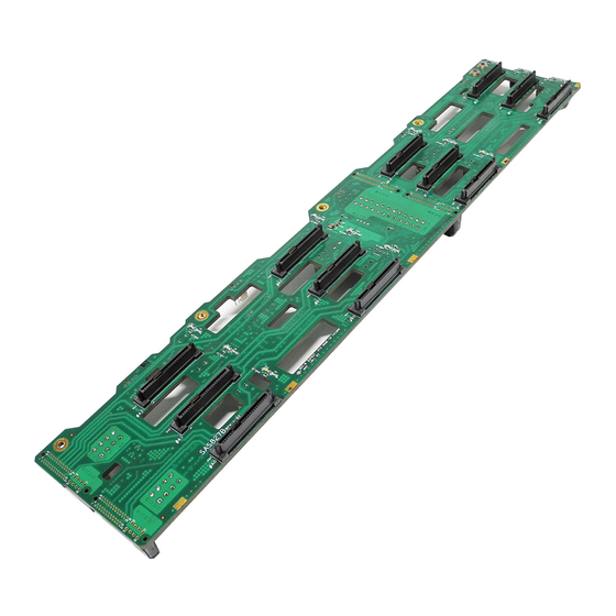
SAS-827B Backplane
SPI
4
JP69
JP56
D1
A
R144
C
TP1
TP3
D76
D71
F15
TP2
C39
44
34
33
C42
C48
MB-D
F19
TP5
F20
F21
F23
F22
C167
C168
C201
11
23
F24
12
22
F25
+
+
R51
F26
F35
C198
C46
C43
D70
D67
DEBUG
J21
F38
C143
C4
JPI2C1
5
R132
C197
+
R128
R69
MB-C
C121
1
D69
D66
R224
USER'S GUIDE
Rev. 1.0
FAN2
C45
F14
+
1
4
SAS827B
CR4
JP55
D65
REV 1.01
DESIGNED IN USA
JP36:
C15
OPEN:DEFAULT
JP35:
CLOSE:ANY POWER BUTTON
OPEN:DEFAULT
C115
CLOSE:LED TEST
JP36
JP35
C58
+
U37
U38
C3
1
1
+
CR13
C19
C119
D59
R49
TO PS
C44
+
+
D63
D58
C21
®
1
F13
4
FAN1
JP54
C266
R217
MB-B
D57
R216
JPW3
F31
8
5
F32
F33
F34
C85
1
4
D61
D56
JF5-AB
R222
C84
MB-A
F27
F28
8
5
F29
F30
D55
D60
4
JPW2
1
Advertisement
Table of Contents

Subscribe to Our Youtube Channel
Related Manuals for Supero SAS-827B


Summary of Contents for Supero SAS-827B
- Page 1 CR13 R188 R187 JP18 BUZZER RESET R135 R134 C119 R133 C198 C159 DEBUG JF5-AB C143 C174 C173 C160 C158 R222 JPI2C1 TO PS R132 C197 MB-A R128 MB-C C200 JF6-CD C121 R224 JPW2 C199 SAS-827B Backplane USER'S GUIDE Rev. 1.0...
- Page 2 SAS-827B Backplane User’s Guide The information in this User’s Manual has been carefully reviewed and is believed to be accurate. The vendor assumes no responsibility for any inaccuracies that may be contained in this document, makes no commitment to update or to keep current the information in this manual, or to notify any person or organization of the updates.
-
Page 3: Table Of Contents
Chapter 1 SAS-827B Safety Guidelines ESD Safety Guidelines ................... 1-1 General Safety Guidelines ................1-1 An Important Note to Users ................1-2 Introduction to the SAS-827B Backplane ............1-2 Chapter 2 Jumpers and Pin Definitions Front Connectors .................... 2-1 Front Connectors .................... 2-1 2-2 Front Jumpers and Pin Definitions.............. -
Page 4: Contacting Supermicro
SAS-827B Backplane User’s Guide Contacting Supermicro Headquarters Address: Super Micro Computer, Inc. 980 Rock Ave. San Jose, CA 95131 U.S.A. Tel: +1 (408) 503-8000 Fax: +1 (408) 503-8008 Email: marketing@supermicro.com (General Information) support@supermicro.com (Technical Support) Web Site: www.supermicro.com Europe Address: Super Micro Computer B.V. -
Page 5: Returning Merchandise For Service
Preface Returning Merchandise for Service A receipt or copy of your invoice marked with the date of purchase is required be- fore any warranty service will be rendered. You can obtain service by calling your vendor for a Returned Merchandise Authorization (RMA) number. When returning to the manufacturer, the RMA number should be prominently displayed on the outside of the shipping carton, and mailed prepaid or hand-carried. - Page 6 SAS-827B Backplane User’s Guide Notes...
-
Page 7: Chapter 1 Sas-827B Safety Guidelines
• Disconnect the power cable before installing or removing any cables from the SAS-827B backplane. • Make sure that the SAS-827B backplane is securely and properly installed on the motherboard to prevent damage to the system due to power shortage. -
Page 8: An Important Note To Users
Introduction to the SAS-827B Backplane The SAS-827B backplane has been designed to utilize the most up-to-date technol- ogy available, providing your system with reliable, high-quality performance. This manual reflects SAS-827B Revision 1.01, the most current release available at the time of publication. -
Page 9: Front Connectors
Chapter 2: Safety Guidelines Chapter 2 Jumpers and Pin Definitions Front Connectors JP57 FAN4 FAN2 JP30: OPEN:45 BAR CODE JP69 FAN1 1-2:50 C DEFAULT FAN3 2-3:55 C269 JP56 SAS827B JP55 C266 JP54 R217 R144 C178 MB-B REV 1.01 R145 R216 DESIGNED IN USA JP30 C176... - Page 10 SAS-827B Backplane User's Guide 1. - 3. Motherboard Power Connectors These connectors, designated JPW1, JPW2, and JPW3 supply power the four motherboard nodes in the chassis. 4. - 7. Chassis Fan Connectors These connectors, designated JP54, JP55, JP56 and JP57 supply power to the chassis.
- Page 11 Chapter 2: Safety Guidelines 13. - 14. Backplane to Front Panel Headers These connectors are designated JF5 and JF6. They connect the backplane to the front LED panels on the chassis. JF5 con- nects to the LED display panel for mother- boards A and B.
-
Page 12: Front Jumpers And Pin Definitions
SAS-827B Backplane User's Guide Front Jumpers and Pin Definitions JP69 JP30 JP57 FAN4 FAN2 JP30: BAR CODE OPEN:45 JP69 FAN1 1-2:50 C DEFAULT FAN3 2-3:55 Buzzer C269 SAS827B JP55 JP54 JP56 C266 R217 R144 MB-B C178 REV 1.01 R216 R145... -
Page 13: Front Led Indicator
Chapter 2: Safety Guidelines Front LED Indicator JP57 FAN4 FAN2 JP30: BAR CODE OPEN:45 JP69 FAN1 1-2:50 C DEFAULT FAN3 2-3:55 C269 SAS827B JP54 JP56 JP55 C266 R217 R144 C178 MB-B REV 1.01 R145 R216 JP30 DESIGNED IN USA C176 C177 JPW3 C203... -
Page 14: Rear Connectors And Led Indicators
SAS-827B Backplane User's Guide Rear Connectors and LED Indicators R177 SAS D2 SAS C2 R182 SAS A2 R174 SAS B2 R178 R173 SAS C1 SAS D1 SAS B2 R165 SAS A1 R148 R164 SAS827T SAS D0 SAS B0 SAS C0 R179 REV 1.01... -
Page 15: Sas Ports
Chapter 2: Safety Guidelines SAS Ports The SAS-827B backplane is designed with four separate sectors, which support from one to four motherboards indepentdently of each other. The SAS ports are used to connect the SAS drive cables. The 12 ports are designated A0, A1, A2, B0, B1, B2, C0, C1, C2 and D0, D1, D2. - Page 16 SAS-827B Backplane User's Guide Disclaimer (cont.) The products sold by Supermicro are not intended for and will not be used in life sup- port systems, medical equipment, nuclear facilities or systems, aircraft, aircraft devices, aircraft/emergency communication devices or other critical systems whose failure to per- form be reasonably expected to result in significant injury or loss of life or catastrophic property damage.
Need help?
Do you have a question about the SAS-827B and is the answer not in the manual?
Questions and answers