Table of Contents
Advertisement
Quick Links
S
UPER
Q4
WWN
ACT22
A
C
U18
C361
C362
J23
U4
5
10
15
20
25
28
E
K
R
Y
AE
AH
4
1
3
UART_S1
1
1
4
1
3
MDIO2
1
EXPDBG2
J24
EC15
FAN2
SEC_J1
BPN-SAS2-847EL2
FAN1
REV: 1.01
4
SEC_J0
1
EC20
EC16
U24
SAS2-847EL BACKPLANE
EC22
EC6
PRI_I2C1
A
C
EC12
ACT21
C130
C129
U3
5
10
15
20
25
28
MDIO1
E
1
K
R
R42
Y
C134
AE
C133
AH
L2
1
SEC_MODE2
ACTLED1
SEC_MODE1
EC13
PRI_J1
PRI_J0
EC8
USER'S GUIDE
Rev. 1.0a
®
EC17
DESIGNED IN USA
J21
2
1
1
EC5
4
1
WWN
4
1
4
JP1
1
BUZZER_ENB1
EC14
EC2
EC3
L1
1
3
3
PRI_MODE2
1
PRI_MODE1
C
FANFAIL_LED_DISABLE
FAN3
FAN4
1
4
A
1
4
FAN_MONITOR_DISABLE
A
1
OVERHEATFAIL1
C
PWR1
GND
GND
+5V
+12V
PWR2
+5V
+12V
GND
GND
EC7
+12V
+5V
GND
GND
BC17
EC9
PWR3
C
C
A
A
PWR5
+12V
GND
GND
+5V
BAR CODE
+12V
GND
GND
+5V
PWR6
Advertisement
Table of Contents

Related Manuals for Supero Supero SAS2-847EL BACKPLANE


Summary of Contents for Supero Supero SAS2-847EL BACKPLANE
- Page 1 UPER ® EC22 EC17 DESIGNED IN USA ACT22 PRI_I2C1 EC12 ACT21 C130 C361 C362 C129 BUZZER_ENB1 MDIO1 EC14 C134 C133 SEC_MODE2 ACTLED1 SEC_MODE1 UART_S1 PRI_MODE2 PRI_MODE1 FANFAIL_LED_DISABLE FAN3 FAN4 MDIO2 EXPDBG2 FAN_MONITOR_DISABLE OVERHEATFAIL1 EC15 EC13 FAN2 PWR1 SEC_J1 PRI_J1 +12V PWR5 +12V PWR2...
- Page 2 This product, including software and documentation, is the property of Supermicro and/or its licensors, and is supplied only under a license. Any use or reproduction of this product is not allowed, except as expressly permitted by the terms of said license.
-
Page 3: Table Of Contents
Safety Information and Technical Specifi cations Table of Contents Contacting Supermicro ..................v Returning Merchandise for Service..............vi Chapter 1 Safety Guidelines ESD Safety Guidelines ................... 1-1 General Safety Guidelines ................1-1 An Important Note to Users ................1-2 Introduction to the SAS2-847EL Backplane............ 1-2 Chapter 2 Connectors, Jumpers and LEDs Front Connectors .................... - Page 4 SAS2-847EL Backplane User's Guide Dual HBA Confi guration Cables ..............3-12 Supported Cascading Confi gurations ............3-13 Dual SAS HBA and Cascaded Confi guration ..........3-14...
-
Page 5: Contacting Supermicro
Super Micro Computer, Inc. 980 Rock Ave. San Jose, CA 95131 U.S.A. Tel: +1 (408) 503-8000 Fax: +1 (408) 503-8008 Email: marketing@supermicro.com (General Information) support@supermicro.com (Technical Support) Web Site: www.supermicro.com Europe Address: Super Micro Computer B.V. Het Sterrenbeeld 28, 5215 ML... -
Page 6: Returning Merchandise For Service
For faster service, RMA authorizations may be requested online (http://www. supermicro.com/support/rma/). Whenever possible, repack the backplane in the original Supermicro box, using the original packaging materials. If these are no longer available, be sure to pack the backplane in an anti-static bag and inside the box. Make sure that there is enough packaging material surrounding the backplane so that it does not become damaged during shipping. -
Page 7: Chapter 1 Safety Guidelines
Safety Information and Technical Specifi cations Chapter 1 Safety Guidelines To avoid personal injury and property damage, carefully follow all the safety steps listed below when accessing your system or handling the components. ESD Safety Guidelines Electrostatic Discharge (ESD) can damage electronic com ponents. To prevent dam- age to your system, it is important to handle it very carefully. -
Page 8: An Important Note To Users
This manual refl ects SAS2-847EL1 and SAS2-847EL2 Revision 1.01, the most current release available at the time of publication. Always refer to the Supermicro Web site at www.supermicro.com for the latest updates, compatible parts and sup- ported confi... -
Page 9: Chapter 2 Connectors, Jumpers And Leds
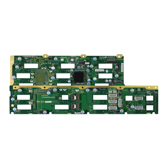
Safety Information and Technical Specifi cations Chapter 2 Connectors, Jumpers and LEDs Front Connectors EC22 EC17 DESIGNED IN USA ACT22 PRI_I2C1 EC12 ACT21 C130 C361 C362 C129 BUZZER_ENB1 MDIO1 EC14 C134 C133 SEC_MODE2 SEC_MODE1 ACTLED1 UART_S1 PRI_MODE2 PRI_MODE1 FAN3 FAN4 FANFAIL_LED_DISABLE MDIO2 EXPDBG2... -
Page 10: Front Connector And Pin Defi Nitions
SAS2-847EL Backplane User's Guide Front Connector and Pin Defi nitions 1. Primary I C Connector C Connector Pin Defi nitions The I C connector is used to monitor the power Pin# Defi nition supply status and to control the fans. See the Data table on the right for pin defi... - Page 11 Safety Information and Technical Specifi cations 6. Fan Connectors Fan Connectors The 4-pin connectors, designated FAN1, Pin# Defi nition through FAN4, provide power to the fans. Ground See the table on the right for pin defi ni- +12V tions. Tachometer Empty 7.
-
Page 12: Front Jumper Locations And Pin Defi Nitions
SAS2-847EL Backplane User's Guide Front Jumper Locations and Pin Defi nitions PRI_MODE1 PRI_MODE2 PRI_MODE1 FAN3 OVERHEATFAIL1 PRI_MODE2 PWR1 +12V EC22 EC17 DESIGNED IN USA ACT22 PRI_I2C1 EXPDBG1 EC12 ACT21 C130 C361 C362 MDI01 C129 UART_P1 BUZZER_ENB1 MDIO1 SEC_MODE2 EC14 BUZZER_ENB1 C134 SEC_MODE1 UART_S1... - Page 13 Safety Information and Technical Specifi cations General Jumper Settings Jumper Jumper Settings Note Factory Setting PRI_MODE1 and 2 Pins 2-3 Do not change Factory Setting SEC_MODE1 and 2 Pins 2-3 Do not change MDI01 and 02 No jumper required SMC internal use only UART_P1 No jumper required Primary UART connector...
-
Page 14: Front Led Indicators
SAS2-847EL Backplane User's Guide Front LED Indicators EC22 EC17 DESIGNED IN USA ACT22 PRI_I2C1 EC12 ACT21 C130 C361 C362 C129 BUZZER_ENB1 MDIO1 EC14 C134 C133 12V_LED1 FANFAIL1 SEC_MODE2 ACTLED1 SEC_MODE1 UART_S1 PRI_MODE2 PRI_MODE1 OVERHEATFAIL1 FAN3 FAN4 FANFAIL_LED_DISABLE MDIO2 EXPDBG2 FAN_MONITOR_DISABLE OVERHEATFAIL1 5V_LED1 EC15... -
Page 15: Rear Connectors And Led Indicators
Safety Information and Technical Specifi cations Rear Connectors and LED Indicators ACT20 PRI_FLASH1 SEC_FLASH1 SAS #20 33 9 SAS #8 SAS #14 SAS #7 SAS #13 SAS #19 ACT12 FAIL12 FAIL6 SAS #18 SAS #6 SAS #12 SAS #2 SAS #5 SAS #17 33 9 SAS #11... - Page 16 SAS2-847EL Backplane User's Guide Rear LED Indicators Rear Connector Hard Drive Activity LED Failure LED SAS #0 ACT #0 FAIL #0 SAS #1 ACT #1 FAIL #1 SAS #2 ACT #2 FAIL #2 SAS #3 ACT #3 FAIL #3 SAS #4 ACT #4 FAIL #4 SAS #5...
-
Page 17: Chapter 3 Dual Port And Cascading Confi Gurations
Safety Information and Technical Specifi cations Chapter 3 Dual Port and Cascading Confi gurations Single and Dual Port Expanders Single Ports SAS2-847EL1 backplanes have a single-port expander that access all hard drives and supports cascading. From HBA or higher backplane EC22 EC17 DESIGNED IN USA... -
Page 18: Failover
SAS2-847EL Backplane User's Guide Failover The SAS2-847EL2 backplane has two expanders which allow effective failover. SAS HBA Single Host Bus Adapter In a single host bus confi guration, the EC22 EC17 ACT22 DESIGNED IN USA PRI_I2C1 ACT21 EC12 C130 C361 C362 C129 backplane connects to one Host Bus... -
Page 19: Failover With Raid Cards And Multiple Hbas
MPIO software. +12V EC20 BC17 +12V PWR3 PWR6 EC16 Contact your Supermicro authorized Primary ports Secondary ports Expander 1 Expander 2 representative for details. Figure 3-3: Dual HBA Failover Confi gurations IMPORTANT: For RAID controllers, redundancy is achieved through port failover. -
Page 20: Chassis Power Card And Support Cables
SAS2-847EL Backplane User's Guide Chassis Power Card and Support Cables Chassis Power Card In a cascaded confi guration, the fi rst chassis includes a motherboard and at least one Host Bus Adapter (HBA). Other servers in this enclosed system, include a power card. -
Page 21: Connecting An Internal Host Bus Adapter To The Backplane
Safety Information and Technical Specifi cations Connecting an Internal Host Bus Adapter to the Backplane The following section lists the most common cables used to connect the HBA to the backplane. EC22 EC17 ACT22 DESIGNED IN USA PRI_I2C1 EC12 ACT21 C130 C361 C362... - Page 22 SAS2-847EL Backplane User's Guide Cable Name: iPass (mini SAS) to iPass (mini SAS) Part #: CBL-0108L-02 Length: 39 cm (15 inches) Part #: CBL-0109L-02 Length: 22 cm (9 inches) Part #: CBL-0110L-02 Length: 18 cm (7 inches) Description: This cable has an iPass (SFF-8087/mini-sas) connector (36 pins) at each end.
-
Page 23: Connecting An External Host Bus Adapter To The Backplane
Safety Information and Technical Specifi cations Connecting an External Host Bus Adapter to the Backplane This backplane supports external Host Bus Adapters. In this confi guration, the HBA and the backplane are in different physical chassis. This allows a JBOD confi gura- tion system to connect to the other system that has a HBA. -
Page 24: Supported External Hba To Backplane Cable
SAS2-847EL Backplane User's Guide Supported External HBA to Backplane Cable Use the following cable if your external HBA has an Infi niBand connector. Figure 3-7: External Cable (CBL-0166L) Cable Name: SAS EL2/EL1 Cascading Cable (External), 68cm Part #: CBL-0166L (SFF-8088 1x to SFF-8088 x1) Ports: Single or Dual Placement: External cable Description: External cascading cable. -
Page 25: Connecting Multiple Backplanes In A Single Channel Environment
Safety Information and Technical Specifi cations Connecting Multiple Backplanes in a Single Channel Environment This section describes the cables used when cascading from a single HBA. These connections use CBL-0167L internal cables and CBL-0166L external cables. EC22 EC17 ACT22 DESIGNED IN USA PRI_I2C1 EC12 ACT21... -
Page 26: Single Hba Confi Guration Cables
SAS2-847EL Backplane User's Guide Single HBA Confi guration Cables Single Port Cable Assembly Figure 3-9: Single Port Internal Cable (CBL-0167L) Cable Name: SAS EL2/EL1 Backplane Cable (Internal) with 2-port Cascading Cable, 68 cm Part #: CBL-0167L (SFF-8087 to SFF-8088 x1) Ports: Single Placement: Internal cable Description: Internal cable. -
Page 27: Connecting Multiple Backplanes In A Dual Channel Environment
Safety Information and Technical Specifi cations Connecting Multiple Backplanes in a Dual Channel Environment This section describes the cables used when cascading from dual HBAs. These connections use CBL-0168L internal cables and CBL-0166L external cables. EC22 EC17 DESIGNED IN USA ACT22 PRI_I2C1 EC12... -
Page 28: Dual Hba Confi Guration Cables
SAS2-847EL Backplane User's Guide Dual HBA Confi guration Cables Dual Port Cable Assembly Figure 3-12: Dual Port Internal Cable (CBL-0168L) Cable Name: SAS Dual-port Cable Assembly, 68/76cm Part #: CBL-0168L Placement: Internal cable Ports: Dual Description: Internal cascading cable. Connects the backplane to the Host Bus Adapter (HBA) or external port. -
Page 29: Supported Cascading Confi Gurations
The fi rst backplane in a cascaded system requires a motherboard and HBA. Other servers require a power control card with no motherboard and no HBA. For more information, see the SC846 Chassis Manual available at www.supermicro.com. EC22 EC17... -
Page 30: Dual Sas Hba And Cascaded Confi Guration
SAS2-847EL Backplane User's Guide Dual SAS HBA and Cascaded Confi guration EC22 EC17 ACT22 DESIGNED IN USA PRI_I2C1 EC12 ACT21 C130 C361 C362 C129 BUZZER_ENB1 MDIO1 EC14 C134 C133 SEC_MODE2 ACTLED1 SEC_MODE1 UART_S1 PRI_MODE2 PRI_MODE1 FANFAIL_LED_DISABLE MDIO2 FAN3 FAN4 EXPDBG2 FAN_MONITOR_DISABLE EC15 OVERHEATFAIL1... - Page 31 Safety Information and Technical Specifi cations Notes 3-15...
- Page 32 SAS2-847EL Backplane User's Guide Disclaimer (cont.) The products sold by Supermicro are not intended for and will not be used in life sup- port systems, medical equipment, nuclear facilities or systems, aircraft, aircraft devices, aircraft/emergency communication devices or other critical systems whose failure to per- form be reasonably expected to result in signifi...
Need help?
Do you have a question about the Supero SAS2-847EL BACKPLANE and is the answer not in the manual?
Questions and answers