Table of Contents
Advertisement
Quick Links
S
UPER
JP18:BUZZER RESET
BZ1
JP18
1
+
J14
SAS747TQ
J16
REV:
1.00
7
7
DESIGNED IN USA
#6
#7
C201
C45
JP13
JP10
+5V
+12V
GND
GND
+12V
GND
1
4
1
SAS-747TQ BACKPLANE
JP68
JP35
JP25
SIDEBAND#2
3
1
3
1
JP35:9072 RST
JP25:OH TEMP.
1-2: RST
OPEN:45
C
2-3: NO RST
1-2:50
C
I2C#2
JP95
2-3:55
C
J12
J10
7
7
#5
#4
C203
C119
FAN#4
JP64
JP63
JP65
1
1
GND
+5V
4
3
1
4
3
1
USER'S GUIDE
Rev. 1.0
Y1
32
17
33
RP3
48
1
3
64
RP1
49
1
3
JP98
JP84:MODE
JP99
1-2:SGPIO
2-3:I2C
J8
J7
7
7
C107
U18
#3
#2
C44
C202
JP56
1
FAN#3
4
3
®
UPGRADE
JP69
U19
5
1
2
6
A
A
A
C
C
C
SIDEBAND#1
1
3
1
JP97
I2C#1
J6
J5
7
7
#1
#0
C3
+
FAN#2
JP62
JP60
FAN#1
1
4
1
4
JP61
Advertisement
Table of Contents

Related Manuals for Supero SAS-747TQ BACKPLANE


Summary of Contents for Supero SAS-747TQ BACKPLANE
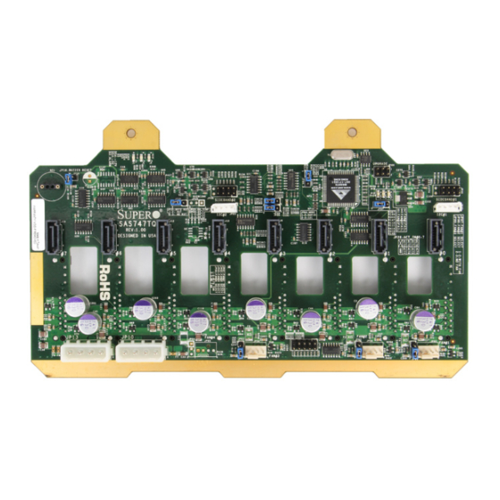
- Page 1 1-2:50 I2C#2 JP95 I2C#1 JP99 1-2:SGPIO 2-3:55 2-3:I2C SAS747TQ REV: 1.00 DESIGNED IN USA C107 C203 C201 C119 C202 JP13 JP10 FAN#2 FAN#4 JP64 JP63 JP62 JP65 JP56 JP60 FAN#1 FAN#3 +12V +12V JP61 SAS-747TQ BACKPLANE USER'S GUIDE Rev. 1.0...
- Page 2 SAS-747TQ Backplane User's Guide The information in this User’s Manual has been carefully reviewed and is believed to be accurate. The vendor assumes no responsibility for any inaccuracies that may be contained in this document, makes no commitment to update or to keep current the information in this manual, or to notify any person or organization of the updates.
-
Page 3: Table Of Contents
ESD Safety Guidelines ................... 1-1 General Safety Guidelines ................1-1 An Important Note to Users ................1-2 Introduction to the SAS-747TQ Backplane ............. 1-2 Chapter 2 Jumper Settings and Pin Definitions ............2-1 Front Connectors and Jumpers ..............2-1 Front Components ..................2-1 Front Connector and Pin Definitions ............... -
Page 4: Contacting Supermicro
SAS-747TQ Backplane User's Guide Contacting Supermicro Headquarters Address: Super Micro Computer, Inc. 980 Rock Ave. San Jose, CA 95131 U.S.A. Tel: +1 (408) 503-8000 Fax: +1 (408) 503-8008 Email: marketing@supermicro.com (General Information) support@supermicro.com (Technical Support) Web Site: www.supermicro.com Europe Address: Super Micro Computer B.V. -
Page 5: Returning Merchandise For Service
Preface Returning Merchandise for Service A receipt or copy of your invoice marked with the date of purchase is required be- fore any warranty service will be rendered. You can obtain service by calling your vendor for a Returned Merchandise Authorization (RMA) number. When returning to the manufacturer, the RMA number should be prominently displayed on the outside of the shipping carton, and mailed prepaid or hand-carried. - Page 6 SAS-747TQ Backplane User's Guide Notes...
-
Page 7: Chapter 1 Safety Guidelines
Chapter 1: Safety Guidelines Chapter 1 Safety Guidelines To avoid personal injury and property damage, carefully follow all the safety steps listed below when accessing your system or handling the components. ESD Safety Guidelines Electrostatic Discharge (ESD) can damage electronic com ponents. To prevent dam- age to your system, it is important to handle it very carefully. -
Page 8: An Important Note To Users
Introduction to the SAS-747TQ Backplane The SAS-747TQ backplane has been designed to utilize the most up-to-date tech- nology available, providing your system with reliable, high-quality performance. This manual reflects SAS-747TQ Revision 1.00, the most current release available at the time of publication. -
Page 9: Chapter 2 Jumper Settings And Pin Definitions
Chapter 2: Jumper Settings and Pin Definitions Chapter 2 Jumper Settings and Pin Definitions Front Connectors and Jumpers UPGRADE JP69 JP18:BUZZER RESET JP18 JP68 JP35 JP25 SIDEBAND#2 SIDEBAND#1 JP35:9072 RST JP25:OH TEMP. JP97 1-2: RST OPEN:45 JP84:MODE JP98 2-3: NO RST 1-2:50 I2C#2 JP95... -
Page 10: Front Connector And Pin Definitions
SAS-747TQ Backplane User's Guide Front Connector and Pin Definitions 1. Upgrade Connector The upgrade connector, designated JP69, is used for manufacturer's diagnostic purposes only. 2. I C Connectors C Connector Pin Definitions The I C connectors, designated JP37 and Pin#... - Page 11 Chapter 2: Jumper Settings and Pin Definitions 5. Backplane Main Power Connectors Backplane Main Power The 4-pin connectors, designated JP66 and 4-Pin Connector JP68 provide power to the backplane. See Pin# Definition the table on the right for pin definitions. +12V 2 and 3 Ground...
-
Page 12: Front Jumper Locations And Pin Definitions
SAS-747TQ Backplane User's Guide Front Jumper Locations and Pin Definitions JP69 JP18 JP84 JP98 UPGRADE JP69 JP18:BUZZER RESET JP18 JP35 JP99 JP35 JP25 JP68 SIDEBAND#2 SIDEBAND#1 JP35:9072 RST JP25:OH TEMP. JP97 JP97 1-2: RST OPEN:45 JP84:MODE JP98 2-3: NO RST... -
Page 13: Fan Jumper Settings
Chapter 2: Jumper Settings and Pin Definitions Socket Settings Socket Socket Setting Note Buzzer reset* JP18 Connected to front panel Press once to disable buzzer Press twice to enable buzzer *The buzzer sound indicates that a condition requiring immediate attention has occurred. -
Page 14: I 2 C And Sgpio Modes And Jumper Settings
SAS-747TQ Backplane User's Guide C and SGPIO Modes and Jumper Settings This backplane can utilize I C or SGPIO. SGPIO is the default mode and can be used without making changes to your jumpers. The following information details which jumpers must be configured to use I C mode or restore your backplane to SGPIO mode. -
Page 15: Front Led Indicators
Chapter 2: Jumper Settings and Pin Definitions UPGRADE Front LED Indicators JP69 +5V LED FAN FAIL #1 #2 #3 LEDs +12V LED ALARM (Red, on) JP97 JP84:MODE 1-2:SGPIO 2-3:I2C UPGRADE JP69 JP18:BUZZER RESET JP18 JP68 JP35 JP25 SIDEBAND#2 JP68 JP35 JP25 SIDEBAND#2 SIDEBAND#1... -
Page 16: Rear Connectors And Led Indicators
SAS-747TQ Backplane User's Guide Rear Connectors and LED Indicators ACT#7 FAIL#7 FAIL#0 ACT#0 FAIL#1 ACT#1 FAIL#2 ACT#2 FAIL#3 ACT#3 FAIL#4 ACT#4 FAIL#5 ACT#5 FAIL#6 ACT#6 R149 R165 R178 R173 R150 R164 Figure 2-4: Rear Connectors Rear SAS/SATA Connectors Rear SAS Drive... - Page 17 Chapter 2: Jumper Settings and Pin Definitions Notes...
- Page 18 SAS-747TQ Backplane User's Guide Disclaimer (cont.) The products sold by Supermicro are not intended for and will not be used in life sup- port systems, medical equipment, nuclear facilities or systems, aircraft, aircraft devices, aircraft/emergency communication devices or other critical systems whose failure to per- form be reasonably expected to result in significant injury or loss of life or catastrophic property damage.
Need help?
Do you have a question about the SAS-747TQ BACKPLANE and is the answer not in the manual?
Questions and answers