Advertisement
Quick Links
Features
•
Wideband EMC Solid State Power Amplifier
•
Small Signal Gain 55dB Typical
•
Output Saturation Power 51.5dBm Typical
•
Supply Voltage 110/220 VAC
•
50 Ohm Matched Input/Output
•
Overvoltage Protection
•
Overcurrent Protection
•
Auto Calibration
Electrical Specifications (T
Gain Variation Over Temperature (0⁰C to +50⁰C)
Output 1dB Compression Point (P1dB)
Saturated Output Power (Psat)
Supply Current (220V AC)
Power Added Efficiency (PAE)
Turn On/Off Speed (Switch Disable)
Turn On/Off Speed (Drain Disable)
Turn On/Off Speed (Gate Disable)
Input / Output Connectors
Rev 4. 06-21-2023 | Subject to change without notice
B0
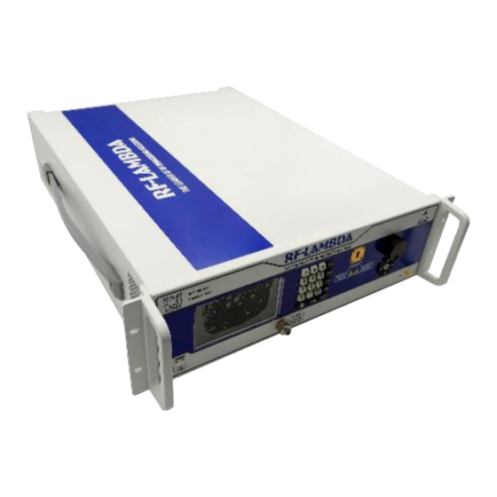
Wideband EMC Benchtop Power Amplifier
18GHz-26.5GHz
=+25⁰C)
A
Parameter
Frequency Range
Small Signal Gain
Gain Flatness
Input VSWR
IM3
Weight
Impedance
Package
Product Description
REMC18G26GD is a wideband EMC power amplifier with a frequency range
of 18 to 26.5GHz.
The power output of this amplifier is 51.5dBm typical. The typical small
signal gain is 55dB with a flatness of ±6dB. This excellent performance is
achieved through the use of GaN devices.
The power amplifier's input connector is 2.92mm-Male and Output
connector is WR42. This product has a calibration feature which enables
customer to obtain great performance through time and temperature
changes.
The operating temperature of this product is with in 0⁰C to +50⁰C.
Typical Applications
•
Wireless Infrastructure
•
Military and Aerospace Applications
•
Test Instrumentation
•
Radar Systems
•
5G Wireless Communications
•
Microwave Radio Systems
•
TR Modules
•
Research and Development
•
Cellular Base Stations
Min
Typ
18
50
55
±6.0
±3.0
1.5
50
50
51.5
-28
10
ON
100
OFF
100
ON
500
OFF
150
ON
1300
OFF
200
56.3 Max.
2.92mm-Male(Input)/WR42 (Output)
(H-Plane available with adapter)
3U Rack-mount/Tabletop Chassis
Sales:
sales@rflambda.com
REMC18G26GD
Max
26.5
5
50
RF-LAMBDA USA LLC:
Technical:
support@rflambda.com
Units
GHz
dB
dB
dB
:1
dBm
dBm
A
dBc
%
ns
ns
us
us
us
us
lbs.
Ohms
www.rflambda.com
Advertisement

Related Manuals for RF-Lambda REMC18G26GD


Summary of Contents for RF-Lambda REMC18G26GD
- Page 1 Wideband EMC Benchtop Power Amplifier 18GHz-26.5GHz Product Description REMC18G26GD is a wideband EMC power amplifier with a frequency range of 18 to 26.5GHz. The power output of this amplifier is 51.5dBm typical. The typical small signal gain is 55dB with a flatness of ±6dB. This excellent performance is achieved through the use of GaN devices.
- Page 2 *Maximum RF input power is set to assure safety of amplifier. Input power may be increased at own risk to achieve full power of amplifier. Please reference gain and power curves. **For vibration testing details please see additional information section. Rev 4. 06-21-2023 | Subject to change without notice RF-LAMBDA USA LLC: www.rflambda.com Sales: sales@rflambda.com Technical: support@rflambda.com...
- Page 3 REMC18G26GD Typical Performance Plots Gain @ +25℃ Input VSWR@+25℃ Isolation @ +25℃ Note: Small signal VNA measurements include attenuators to protect equipment Rev 4. 06-21-2023 | Subject to change without notice RF-LAMBDA USA LLC: www.rflambda.com Sales: sales@rflambda.com Technical: support@rflambda.com...
- Page 4 REMC18G26GD Typical Performance Plots Gain vs. Output Power CW PndB vs. Frequency CW Saturation Power vs. Frequency CW Pout vs. Pin Rev 4. 06-21-2023 | Subject to change without notice RF-LAMBDA USA LLC: www.rflambda.com Sales: sales@rflambda.com Technical: support@rflambda.com...
- Page 5 Typical Performance Plots Left IM3 vs. Pout Right IM3 vs. Pout Delta IM3 vs. Pout Note: IM3 test performed with 1MHz tone spacing Rev 4. 06-21-2023 | Subject to change without notice RF-LAMBDA USA LLC: www.rflambda.com Sales: sales@rflambda.com Technical: support@rflambda.com...
- Page 6 The Switching Rise Time is 100 ns @+25℃ Switch control port: D-sub 15 PIN #10(Switch Disable) . The yellow curve is the switch control signal, the blue curve is RF output envelope. Rev 4. 06-21-2023 | Subject to change without notice RF-LAMBDA USA LLC: www.rflambda.com Sales: sales@rflambda.com Technical: support@rflambda.com...
- Page 7 LAN Port(remote control) USB-B Port(remote control) USB-A Port (work log) USB-A Port (N/A) Main AC connector AC power supply switch GND connector -40dB Coupling Rev 4. 06-21-2023 | Subject to change without notice RF-LAMBDA USA LLC: www.rflambda.com Sales: sales@rflambda.com Technical: support@rflambda.com...
- Page 8 To eliminate the error code, press “RESET” on front panel keypad to reboot the instrument and clear the alarms. If error code can not be eliminated after reboot, please contact support@rflambda.com Rev 4. 06-21-2023 | Subject to change without notice RF-LAMBDA USA LLC: www.rflambda.com Sales: sales@rflambda.com...
- Page 9 “[5] IP Set” enters IP display page “[6] Product Info” displays product information All action functions will ask for confirming execution when selected from function selection menu. Rev 4. 06-21-2023 | Subject to change without notice RF-LAMBDA USA LLC: www.rflambda.com Sales: sales@rflambda.com Technical: support@rflambda.com...
- Page 10 Power Supply +5V DC is provided for reference * Notes: • HIGH/LOW voltages are standard TTL signals 0.0V-0.8V = LOW. 2.8V-5V = HIGH. Rev 4. 06-21-2023 | Subject to change without notice RF-LAMBDA USA LLC: www.rflambda.com Sales: sales@rflambda.com Technical: support@rflambda.com...
-
Page 11: Outline Drawing
Fig c. Waveguide to coaxial adapter (RFWA42A0COAL) (Consulting sales) Fig d. Waveguide twist (RFWTWWR42) (Consulting sales) Fig a. Fig b. Fig c. Fig d. Rev 4. 06-21-2023 | Subject to change without notice RF-LAMBDA USA LLC: www.rflambda.com Sales: sales@rflambda.com Technical: support@rflambda.com... - Page 12 RF-Lambda products are not warranted or authorized for use as critical components in medical, life-saving, or life sustaining applications, or other applications where a failure would reasonably be expected to cause severe personal injury or death.
Need help?
Do you have a question about the REMC18G26GD and is the answer not in the manual?
Questions and answers