Table of Contents
Advertisement
Quick Links
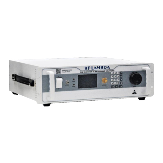
RF-LAMBDA
The power beyond expectations
75W Solid State EMC Benchtop Power Amplifier
Electrical Specifications, T
Frequency Range
Gain Variation Over Temperature
Input Return Loss
Output Return Loss
Saturated Output Power (Psat)
Input Max Power (No Damage)
Power Supply Connector
Input / Output Connectors
Rev 1. 03-25-19
℃
=25
A
Parameter
Gain
(-45 ~ +85)
Isolation S12
Weight
Impedance
Material
12GHz~17GHz
Features
•
Automatic Calibration
•
Built in Temperature Compensation
•
Adjustable Attenuation:
31.5dB Range, 0.5dB Step Size
•
Supply Voltage: 110V/220V AC
Typical Applications
•
Aerospace and military applications
•
Test and Measurement.
•
Research and Development.
Typical
12 ~ 15
52
±3
13
10
49
65
Psat – Gain
35
50
D-SUB COMBO 3POS
SMA Female
Aluminum / Copper
REMC12G17GD
15 ~ 17
55
±3
20
10
49
70
RF-LAMBDA INC.
Sales: sales@rflambda.com
Technical : support@rflambda.com
Units
GHz
dB
dB
dB
dB
dBm
dB
dBm
lbs
Ohms
www.rflambda.com
Advertisement
Table of Contents

Related Manuals for RF-Lambda REMC12G17GD


Summary of Contents for RF-Lambda REMC12G17GD
- Page 1 RF-LAMBDA REMC12G17GD The power beyond expectations 75W Solid State EMC Benchtop Power Amplifier 12GHz~17GHz Features • Automatic Calibration • Built in Temperature Compensation • Adjustable Attenuation: 31.5dB Range, 0.5dB Step Size • Supply Voltage: 110V/220V AC Typical Applications • Aerospace and military applications •...
- Page 2 RF-LAMBDA REMC12G17GD The power beyond expectations Absolute Maximum Ratings Biasing Up Procedure Supply Voltage 110V 220v ac Connect input and output with 50 Ohm RF Input Power (RFIN) Step 1 source/load. ( in band VSWR<1.9:1 or >10dB Psat – Gain...
-
Page 3: Ordering Information
RF-LAMBDA REMC12G17GD The power beyond expectations Ordering Information Part No. Description 12GHz~17GHz REMC12G17GD Power Amplifier Amplifier Use Ensure that the amplifier input and output ports are safely terminated into a proper 50 ohm load before turning on the power. Never operate the amplifier without a load. A proper 50 ohm load is defined as a load with impedance less than 1.9:1 or return loss larger than 10dB relative to 50 Ohm within the specified operating band width. - Page 4 RF-LAMBDA REMC12G17GD The power beyond expectations Gain vs Frequency Frequency (GHz) Output Power vs Frequency Frequency (GHz) RF-LAMBDA INC. www.rflambda.com Rev 1. 03-25-19 Sales: sales@rflambda.com Technical : support@rflambda.com...
-
Page 5: Outline Drawing
RF-Lambda products are not warranted or authorized for use as critical components in medical, life-saving, or life sustaining applications, or other applications where a failure would reasonably be expected to cause severe personal injury or death. -
Page 6: Front Panel
RF-LAMBDA REMC12G17GD The power beyond expectations EMC Equipment User Manual Front Panel ON/OFF switch Power Indicator Alarm Indicator Keypad Gain Adjustment Knob RF Output RF Input Rear Panel Instrument AC power supply switch Fuse Holder Main AC connector GND connector USER CONTROL, D-SUB Connector low-voltage (3.3V) TTL control signals. - Page 7 RF-LAMBDA REMC12G17GD The power beyond expectations Front Panel LCD Screen Display Switching On Instrument Please follow the instructions on the front panel LCD screen after switching on the power. Press “1” on keypad to continue. Self Calibration Screen Calibration is may be recommended “[1] Calibrate”...
- Page 8 RF-LAMBDA REMC12G17GD The power beyond expectations Instrument Status Display Page Indicates instrument RF output status. It will display: Output is Ready to Turn on or RF Output is ON Instrument temperature RF output attenuation (change with adjustment knob) RF input signal center frequency Instrument RF output power Press “Menu”...
- Page 9 RF-LAMBDA REMC12G17GD The power beyond expectations User Control Connector on Rear Panel Pin # Name Function Initial State Description Applied Reset Control Resets PA when logic LOW is applied and released Driver Disable Control Appling logic HIGH disables driver of amplifiers...
Need help?
Do you have a question about the REMC12G17GD and is the answer not in the manual?
Questions and answers