Table of Contents
Advertisement
Quick Links
OPERATOR'S MANUAL
R
INCLUDING: OPERATION, INSTALLATION & MAINTENANCE
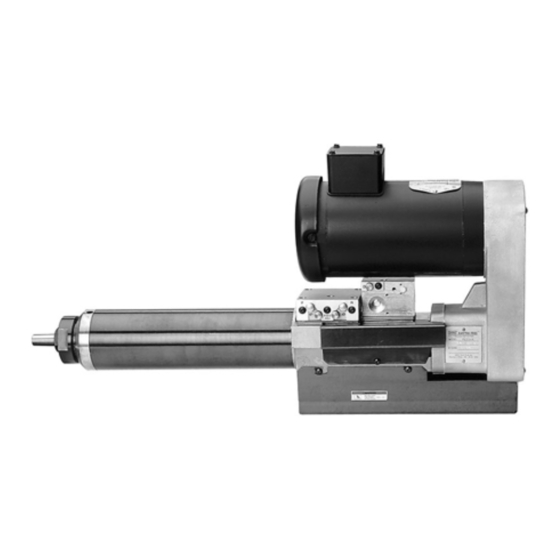
SERIES 7 ELECTRA–FEED DRILL
It is the responsibility of the employer to place this information in the hands of the operator. Keep for future reference.
OPERATING AND SAFETY PRECAUTIONS
•
Keep hands and clothing away from rotating end of tool and all
moving parts of the tool.
•
Wear suitable eye protection while operating tool or when
near tool when it is being operated.
•
Disconnect air and electrical supply from tool before remov-
ing/installing bits or performing other maintenance or service
procedures.
ROUTINE LUBRICATION REQUIREMENTS
When this tool was built, an "O" ring lubricant was applied to all ap-
propriate dynamic seals to insure continued operation. Drive train
components and bearings were also supplied / filled with grease
to insure appropriate life of components. As long as all exterior
seals and wipers are maintained in good working order and all
covers and breather vents are kept in place, it is reasonable to ex-
pect that external debris will not enter the tool. It is also reason-
able to expect that lubricants applied to the tool interior will require
replenishment for at least 5000 hours of normal operation.
Adding spindle oil to the power air inlet of this tool is not
necessary.
MOUNTING
Mounting clamps 49690 and 46982–1 are available for mounting
of this tool. These items are shown on page 11. Both mounts allow
the clamp to grip the outer sleeve of the tool and feature keyways
for alignment.
For parts and service information, contact your local ARO distributor, or the Customer Service Dept. of the Ingersoll–Rand Distribution
Center, White House, TN at PH: (615) 672–0321, FAX: (615) 672–0801.
ARO Tool Products
Ingersoll–Rand Company
1725 U.S. No. 1 North D P.O. Box 8000 D Southern Pines, NC 28388–8000
E1999 INGERSOLL–RAND COMPANY D PRINTED IN U.S.A.
Models FE074B–( )–A( )
READ THIS MANUAL CAREFULLY BEFORE INSTALLING,
OPERATING OR SERVICING THIS EQUIPMENT.
AIR SUPPLY REQUIREMENTS
For maximum operating efficiency, the following air supply specifi-
cations should be maintained to this air tool:
•
AIR PRESSURE – 90 PSIG (6 bar)
•
AIR FILTRATION – 50 micron
•
HOSE SIZE – 5/16" (8 mm) I.D.
An AROR model P29231–110 air line FILTER/REGULATOR plus
100067 gauge is recommended to maintain the above air supply
specifications.
RECOMMENDED LUBRICANTS
After disassembly is complete, all parts, except sealed or shielded
bearings, should be washed with solvent. To relubricate parts, or
for routine lubrication, use the following recommended lubricants:
Where Used
ARO Part #
''O" Rings, Lip Seals
36460
and Air Cylinder
Sliding Splines and
33153
Bearings
SECTION
M107
MANUAL
26
Released: 5-15-98
Revised: 11-20-99
49999-543
Description
4 oz. Stringy Lubricant
5 lb. ''EP" – NLGI #1
Grease
Advertisement
Table of Contents

Subscribe to Our Youtube Channel
Related Manuals for Ingersoll-Rand ARO 7 Series


Summary of Contents for Ingersoll-Rand ARO 7 Series
- Page 1 SECTION M107 OPERATOR’S MANUAL MANUAL INCLUDING: OPERATION, INSTALLATION & MAINTENANCE Released: 5-15-98 Revised: 11-20-99 SERIES 7 ELECTRA–FEED DRILL 49999-543 Models FE074B–( )–A( ) READ THIS MANUAL CAREFULLY BEFORE INSTALLING, OPERATING OR SERVICING THIS EQUIPMENT. It is the responsibility of the employer to place this information in the hands of the operator. Keep for future reference. OPERATING AND SAFETY PRECAUTIONS AIR SUPPLY REQUIREMENTS •...
-
Page 2: Installation
MODEL IDENTIFICATION FE 07 4 B– XX X –A ELECTRIC SELF–FEED TOOL CONTROL CODE A – VALVE IN HEAD HORSEPOWER MOTOR CODE (item 11) 07 = .75 B = 49685–5 (3600 r.p.m.) STROKE LENGTH C = 49685–6 (1800 r.p.m.) 4 = 4” maximum D = 49685–7 (3600 r.p.m.) E = 49685–8 (1800 r.p.m.) TOOL GENERATION... - Page 3 M107 ELECTRICAL CONNECTION DIAGRAM 3 PHASE, 50 / 60 Hz spindle fails to rotate or rotates in the wrong direction, de–ener- gize the motor starter immediately. Turn off the power supply and recheck the wiring. SET–UP PROCEDURE WARNING: Keep clear of rotating end of unit with hands and/or clothing.
- Page 4 DISASSEMBLY/ASSEMBLY INSTRUCTIONS PULLEY SPINDLE SECTION ASSEMBLY _ Assemble spring washer (53) and plate (52) to quill (55), se- curing with plate nut (51). _ Assemble square seal (50) to quill (55). _ Assemble felt seal (24) to lock screw (25). _ Assemble bearing (21) to ‘‘pulley”...
- Page 5 M107 PART NUMBER FOR ORDERING PART NUMBER FOR ORDERING Button Head Screw (4 req’d) ... 49688 Quill ....... . 49630 Drive Housing Cover Bearing...
- Page 6 f 74 Q 45 37 Q Q 54 Q 50 26 Q 25 Q 49 Q 48 Q 39 24 Q 67 Q 61 Q...
- Page 7 M107 ASSEMBLE WITH LOCTITE 290 AND TIGHTEN TO 50 – 60 IN. LBS. ASSEMBLE WITH LOCTITE 242. INCLUDED IN 49595 SERVICE KIT. NOT SHOWN 30131–2 WRENCH Q INCLUDED IN 49594 SERVICE KIT. 49530 WARNING LABEL (2 REQ’D) 49684 LOGO PLATE f INCLUDED IN 49596 SERVICE KIT.
-
Page 8: Manifold Assembly
49775 MANIFOLD ASSEMBLY INCLUDED IN 49595 SERVICE KIT. * NOT INCLUDED IN ASSEMBLY MANIFOLD DISASSEMBLY MANIFOLD ASSEMBLY _ Spring (80), ball (81) and needle valve (86) can be serviced _ Lubricate all ‘‘O” rings with ARO 36460 lube when assem- without removing the manifold from the tool. -
Page 9: Control Disassembly
M107 49674 CONTROL ASSEMBLY 1/8–27 NPT f INCLUDED IN 49596 SERVICE KIT. * NOT INCLUDED IN ASSEMBLY CONTROL DISASSEMBLY _ Control valves (100) and needle valves (103) can be serviced _ Assemble ‘‘O” rings (96) to grooves in end caps (95). without removing the control assembly from the tool. - Page 10 HYDRAULIC CHECK SET–UP HYDRAULIC STROKE CHECK LENGTH 38922 1” ‘‘F” FEED CONTROL VALVE (103) 38922–1 2” 38922–2 3” ‘‘W” ‘‘Y” ‘‘X” CAP SCREW (28) HYDRAULIC CHECK FEED RATE ADJUSTMENT SET–UP PROCEDURE • Assemble hydraulic check to yoke assembly (27). plate. •...
- Page 11 M107 ACCESSORIES $.01 1.88 49690 CLAMP ASSEMBLY (48 mm) 3 (76 mm) 9/32" DIA. THRU C'BORE 7/16" $.01 DIA. x DEPTH SHOWN (4 HOLES) 2.25 (57 mm) $.005 4.360 (111 $.0010 Y99-53 CAP SCREW (4 REQ'D) 49691 CLAMP 2.9815 (76 mm) $.01 4.78 (121 mm) $.005...
-
Page 12: Cross Section
CROSS SECTION PN 49999–543...
Need help?
Do you have a question about the ARO 7 Series and is the answer not in the manual?
Questions and answers