Advertisement
Quick Links
OPERATION AND MAINTENANCE MANUAL
IMPORTANT SAFETY INFORMATION ENCLOSED.
READ THIS MANUAL BEFORE OPERATING TOOL.
FAILURE TO OBSERVE THE FOLLOWING WARNINGS COULD RESULT IN INJURY.
Always operate, inspect and maintain this tool in
accordance with American National Standards
Institute Safety Code for Portable Air Tools
(ANSI–B186.1).
For safety, top performance and maximum
durability of parts, operate this tool at 90 psig
(6.2 bar/620 kPa) maximum air pressure at the
inlet with 3/8" (10 mm) inside diameter air supply
hose.
Air powered tools can vibrate in use. Vibration,
repetitive motions or uncomfortable positions may
be harmful to your hands and arms. Stop using any
tool if discomfort, tingling feeling or pain occurs.
Seek medical advice before resuming use.
Always turn off the air supply and disconnect the
air supply hose before installing, removing or
The use of other than genuine Ingersoll–Rand replacement parts may result in safety hazards, decreased tool
performance, and increased maintenance, and may invalidate all warranties.
Ingersoll–Rand is not responsible for customer modification of tools for applications on which Ingersoll–Rand was not
consulted.
Repairs should be made only by authorized trained personnel. Consult your nearest Ingersoll–Rand Authorized
Servicenter.
It is the responsibility of the employer to place the information in this manual into the hands of the operator.
Refer All Communications to the Nearest
Ingersoll–Rand Office or Distributor.
E Ingersoll–Rand Company 1994
Printed in U.S.A.
for
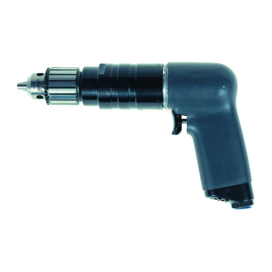
SERIES 7 AIR DRILLS
TPD1388
adjusting any accessory on this tool, or before
performing any maintenance on this tool.
Keep hands, loose clothing and long hair away
from rotating end of tool.
Anticipate and be alert for sudden changes in
motion during start up and operation of any power
tool.
Tool accessory may continue to rotate briefly after
throttle is released.
Do not lubricate tools with flammable or volatile
liquids such as kerosene, diesel or jet fuel.
Do not remove any labels. Replace any damaged
label.
Use accessories recommended by Ingersoll–Rand.
Always use a Dead Handle (47) with Models 7AN4
and 7AQ4.
03530896
Form P6532
Edition 10
February, 1994
Advertisement

Related Manuals for Ingersoll-Rand 7AD1


Summary of Contents for Ingersoll-Rand 7AD1
- Page 1 03530896 Form P6532 Edition 10 February, 1994 OPERATION AND MAINTENANCE MANUAL SERIES 7 AIR DRILLS TPD1388 IMPORTANT SAFETY INFORMATION ENCLOSED. READ THIS MANUAL BEFORE OPERATING TOOL. FAILURE TO OBSERVE THE FOLLOWING WARNINGS COULD RESULT IN INJURY. Always operate, inspect and maintain this tool in adjusting any accessory on this tool, or before accordance with American National Standards performing any maintenance on this tool.
-
Page 2: Warning Label Identification
WARNING LABEL IDENTIFICATION FAILURE TO OBSERVE THE FOLLOWING WARNINGS COULD RESULT IN INJURY. -
Page 3: Installation
Series 7 Air Drills are designed for drilling operations in the aerospace, automotive, appliance, electronic, machining and furniture industries. HOW TO ORDER AN AIR DRILL PISTOL GRIP HANDLE Free Speed Chuck Capacity Model 7AD1 20 000 7AH1 6 000 7AJ1 4 800 7AJJ1... - Page 4 (Dwg. TPA786–5)
- Page 5 PART NUMBER FOR ORDERING PART NUMBER FOR ORDERING Motor Housing Assembly ....7AH–A40A Bearing Spring Washer (2) ....7AH–278 Warning Label .
- Page 6 PART NUMBER FOR ORDERING PART NUMBER FOR ORDERING Gear Head Drill Chuck for M ratio (16 teeth) ..7AM–216 0 to 1/4” capacity ... . . R00A–99 for N ratio (10 teeth) .
- Page 7 MAINTENANCE SECTION 4. While holding the Drill horizontally, carefully unscrew the Gear Case by hand and pull it away from the Motor Housing. Always wear eye protection when operating or 5. For D, H, J, JJ or K ratio, hold the Gear Case performing maintenance on this tool.
- Page 8 MAINTENANCE SECTION 16. While supporting the Front End Plate (21) between 3. Whenever grasping a tool or part in a vise, always use two blocks of wood on the table of an arbor press, leather–covered or copper–covered vise jaws. Take press the Rotor from the Front Rotor Bearing (23).
- Page 9 MAINTENANCE SECTION Put a few drops of Loctite No. 601 Sealant in the Inject a little of the recommended grease in the counterbore surrounding the outside diameter of Bearing. the Bushing. 13. Slide the Front End Plate (21), flat side first, over the d.
- Page 10 MAINTENANCE SECTION 27. Place the Grease Shield (42) against the Spindle Housing Spacer (27) into the Gear Case. Bearing so that the outer rim of the Grease Shield 34. For H, J or JJ ratio, place the Rotor Pinion Spacer slides over the outer ring of the Bearing.
-
Page 11: Troubleshooting Guide
MAINTENANCE SECTION TROUBLESHOOTING GUIDE Trouble Probable Cause Solution Loss of Power Low Air Pressure Check air supply. For top performance, the air pressure must be 90 psig (6.2 bar/620 kPa) at the inlet. Plugged Air Strainer Screen Clean the Air Strainer Screen in a clean, suitable cleaning solution.
Need help?
Do you have a question about the 7AD1 and is the answer not in the manual?
Questions and answers