Table of Contents
Advertisement
Quick Links
Advertisement
Chapters
Table of Contents

Related Manuals for YASKAWA VS-616PS5 Series


Summary of Contents for YASKAWA VS-616PS5 Series
- Page 1 VS-616PS5 Series Installation & Quick-start Manual Brushless Motor Drive...
- Page 2 Any warnings provided by YASKAWA must be promptly provided to the end user. YASKAWA offers an express warranty only as to the quality of its products in conforming to standards and specifications published in YASKAWA’s manual. NO OTHER WARRANTY, EXPRESS OR IMPLIED, IS OFFERED.
- Page 3 240 VAC maximum (for 230 VAC class units). NOTICE NOTICE The information contained within this document is the proprietary property of Yaskawa Electric America, Inc. This information may not be copied, reproduced, or transmitted to other parties without the expressed written authorization of Yaskawa Electric America, Inc.
- Page 4 General Connection Diagram (3 Wire Control W/Standard Hall Sensor Fdbk) Supply Power User Supplied Disconnect VS-616PS5 Brushless Motor Hall Effect Rev.C Encoder For this configuration, For 2 wire configuration set A1-03 to 3330 reference parameter AI-03. +12VDC START Black STOP Brown Orange Yellow...
-
Page 5: Quick Start
Example of Quick Start Motor Data Entry (See page 35 for complete explanation) Parameter Name Description Example E1-01 Input Voltage Setting Set equal to the input supply voltage in VAC RMS E1-02 Motor Capacity Set to 1000 for manual entry of the following “E1” parameters 1000 E1-03 Rated Motor Voltage... - Page 6 VS-616PS5 QUICK START VS-616PS5 QUICK START Personnel who are experienced in the use of VS-616PS5 inverters and motors may use this procedure. NOTE: Do not use this procedure if the inverter has been programmed for a particular application by an Original Equipment Manufacturer or if the inverter has already been programmed for your application.
- Page 7 Operation Plan for Test Run POWER SPEED SPEED FWD JOG STOP Description Key Sequence Digital Operator Display Power ON Ÿ Displays Frequency P 0 0. Reference Value REMOTE LED OFF FWD LED ON Operation Source LOCAL Ÿ Select LOCAL Mode REMOTE Set JOG Reference Ÿ...
-
Page 8: Table Of Contents
(PM) brushless motor. In the PM motor, current is directly related to torque. With power outputs ranging from 0.5 to 500 horsepower (HP), the VS-616PS5 series is suitable for any application. The inverters provide full start-up torque, smooth low speed operation, and precise speed control from zero to full speed. The proprietary auto-tuning function allows the inverters to get the best performance from PM motors manufactured world- wide. - Page 9 This page left intentionally blank.
-
Page 10: Preparation
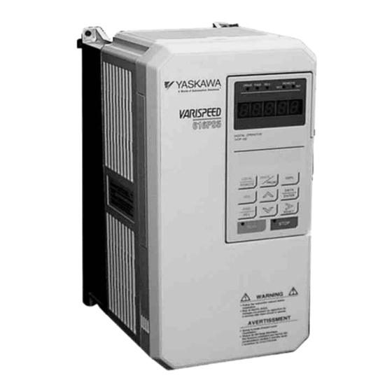
• Check the unit for physical damage that may have occurred during shipping. If any part of the drive is damaged, notify the freight carrier and your Yaskawa representative immediately. • Inspect the drive to determine if any parts have come loose during shipment. Check the screws, covers, components, etc. - Page 11 Identifying the Parts Figure 3 Parts Identification- Model CIMR-PS5U43P7 Removing the Digital Operator To remove the digital operator from the unit: • Push the operator retaining lever in the direction shown by arrow 1 • Lift the digital operator in the direction shown by arrow 2 Cover Bottom Cover...
-
Page 12: Specifications
1.2 Specifications The Rated Current of the inverter must be equal to or greater than the Rated Current of the motor, regardless of the nom- inal horsepower ratings. 230 VAC Units 0.5 thru 20 HP Inverter Model VS-616PS5 CIMR-PS5U 20P4 20P7 21P5 22P2... - Page 13 General Specifications Control Characteristics Control Method Sine Wave PWM, Flux Vector Starting Torque 150% at 1% speed Speed Control Range 100 : 1 (Constant Power Excluded) Speed Control Accuracy +/- 0.02% Torque Limit Independent Quadrant Settings 0 - 300% Frequency Control Range 0.1 to 200 Hertz Frequency Accuracy Analog Speed Command 0.1% Digital Speed Command 0.01%...
-
Page 14: Installation
SECTION 2 SECTION 2 INSTALLATION INSTALLATION 2.1 Mounting Considerations ..............13 Precautions..................13 Choosing a Location ................13 Thermal Considerations..............14 Clearances..................14 Dimensions ..................15 Open Chassis Dimensions and Heat Loss ......... 15 NEMA 1 Dimensions................16 2.1 Mounting Considerations Precautions Observe these precautions to avoid damage to the equipment: •... -
Page 15: Thermal Considerations
2.2 Thermal Considerations Clearances When mounting the VS-616PS5, allow sufficient clearances for effective cooling as shown below: 1.97in (50mm) 4.72in (120mm) 1.18in (30mm) 4.72in (120mm) 1.97in (50mm) Front View Side View NOTES: 1. Required clearances at the top, bottom, and sides of the inverter apply to both open chassis and NEMA 1 enclosed models. -
Page 16: Dimensions
2.3 Dimensions and Heat Loss Open Chassis Type (IP00) Note: All units up to model CIMR-PSU4045 are stocked and shipped as NEMA1 units. Model Open Chassis Dimensions in inches (mm) Mass Heat loss (W) Heat Inside Total CIMR- Lbs (kg) Voltage Sink Unit... - Page 17 Enclosed Type NEMA 1 (IP20) Note: All units up to model CIMR-PSU4045 are stocked and shipped as NEMA1 units. Model NEMA 1 Dimensions in inches (mm) Mass Voltage CIMR- Lbs (kg) 20P4 20P7 5.51 (140) 11.02 (280) 6.30 (160) 4.96 (126) 10.47 (266) 0.28(7) 6.5(3) 21P5...
-
Page 18: Wiring
SECTION 3 SECTION 3 WIRING WIRING 3.1 Wiring Considerations ................17 Precautions ..................17 Inspection .....................17 Main Circuit Diagrams ................18 3.2 Connecting the Supply Power .............19 Input Circuit Requirements..............19 Grounding.....................19 3.3 Connecting the Motor ................20 Output Circuit Considerations...............20 3.4 Connecting the Feedback..............21 Types of Feedback Device ..............21 Types of Feedback Card ..............21 PG-H2 Hall Sensor Feedback Card ............22... -
Page 19: Main Circuit Diagrams
Main Circuit Diagrams PS5U20P4 thru 21P5, PS5U40P4 thru 41P5 PS5U4018 thru 4045 ⊕3 (optional ⊕1 reactor) ⊕1 ⊕2 ⊕2 Power Supply Control Circuit Cooling Fan Power Supply Control Circuit Internal Cooling Fan PS5U22P2 thru 27P5, PS5U42P2 thru 4015 PS5U4055 thru 4160 ⊕3 (optional B1 B2... -
Page 20: Connecting Supply Power
Connecting the Power Supply Input Circuit Requirements The input power supply phases (L1, L2, and L3) may be connected in any sequence. 1. Circuit Breaker or Disconnect • The user must supply a circuit breaker or disconnect with properly sized fuses to protect the input wiring to the VS-616PS5 inverter. -
Page 21: Connecting The Motor
Input Fuse Protection The input diode bridge should be protected from failure, in the event of a short circuit in the inverter, by installing high-speed fuses (Semiconductor Type) on the input. These fuses are for short circuit protection only. They DO NOT take the place of the protection for the wiring, which is supplied by the approved fused disconnect or circuit breaker discussed previously, and is sized according to national, state, and local electrical codes. -
Page 22: Connecting The Feedback
Connecting the Feedback The PS5 operates in a closed loop control method only. A PG feedback option PCB is therefore required. Refer to the following information to properly select and configure the feedback option. Additional connection dia- grams are located in Appendix C. Types of Feedback Device 1. -
Page 23: Pg-H2 Hall Sensor Feedback Card
PG-H2 Hall Sensor Feedback Card The PG-H2 is intended for use with Permanent Magnet motors with integrated Hall-effect sensors. It uses 3 com- mutation channels with 120 electrical degree separation, and 2 speed channels in quadrature. All outputs of the Hall-effect feedback device are in a sinking configuration. -
Page 24: Pg-P2 Encoder Feedback Card With Commutation Encoder
PG-P2 Encoder Feedback Card with Commutation Encoder (PG-P2 revision C) The PG-P2 Encoder Feedback card accepts line driver signals from a commutation encoder. The commutation channels S1, S2, and S3 are wired to HS1, HS2, and HS3. The speed and direction channels are wired to the A, B, and Z line driver outputs of the encoder. -
Page 25: Connecting Control Circuits
Connecting the Control Circuits Control Terminals Layout 12 (G) Control Circuit Wiring The table below outlines the functions of the control circuit terminals. Classifi- Termi- Signal Function Description Signal Level cation Forward run/stop Forward run when closed, stop when open Reverse run/stop Reverse run when closed, stop when open Fault when closed, normal... - Page 26 VS-616PS5 Standard Connection Diagram 230V: 0.4 ~ 15kW 460V: 0.4 ~ 300kW ⊕P3 Gate Drive 1 - Fwd Run when CLOSED Encoder/ Fixed 2 - Rev Run when CLOSED PG-P2 Hall Sensor PG-H2 0~±10V Multi-Function Multi-Function ±9 bit Analog Outputs Inputs 0~±10V 11 (Com)
-
Page 27: Connecting Resistor Braking Units
Connecting Resistor Braking Units 230V: PS5U20P4 to 27P5 Overload Relay Trip Contact 460V: PS5U40P4 to 4015 Braking Resistor Unit MCCB THRX Overload Relay Trip Contact of Braking Resistor Unit THRX Fault Contact Braking Unit 230V: PS5U2011 to 2015 460V: PS5U4018 to 4045 Braking Unit Braking Resistor Unit... -
Page 28: Initial Operation
SECTION 4 SECTION 4 INITIAL OPERATION INITIAL OPERATION 4.1 Operational Concerns ................27 Before Initial Operation ................27 Replacing the Digital Operator ...............27 4.2 Digital Operator ..................28 Orientation....................28 Parameter Entry ..................29 4.3 Entering the Initial Data................30 4.4 Initial Operation by Digital Operator ............31 4.5 Initial Operation by Control Circuits............32 Operational Concerns Before Initial Operation... -
Page 29: Digital Operator
Digital Operator Orientation All functions of the VS-616PS5 are accessed using the digital operator. Below are descriptions of the display and keypad sections. Mode Indicator LEDs DRIVE Mode LED Lights when selecting drive mode (operation is possible). OFF when selecting any other mode. Rotation Direction LEDs FWD: Lights at forward run. -
Page 30: Parameter Entry
Parameter Entry P 00.00 When power is applied, the display defaults to the reference setting: DRIVE PRGM A1-01 Press the key to access the parameters. is displayed. DATA 0002 Press the key to display the value. The default is: ENTER The first 0 will be blinking. -
Page 31: Entering Initial Data
Entering the Initial Data Quick Start Parameters Parameter A1-01 sets the access level for the parameters. Setting it to “0000” disables access to any other changeable parameters. Setting A1-01 to “0002”, which is the factory default setting, enables access to the Quick Start parameters, which are used to initially get the inverter and motor into operation. -
Page 32: Initial Operation By Digital Operator
4.4 Initial Operation by Digital Operator POWER SPEED SPEED FWD JOG STOP Description Key Sequence Digital Operator Display Power ON P 0 0. Ÿ Displays Frequency Reference Value REMOTE LED OFF FWD LED ON Operation Source Ÿ Select LOCAL Mode LOCAL REMOTE Set JOG Reference... -
Page 33: Initial Operation By Control Circuits
4.5 Initial Operation by Control Circuits For operation from the control input terminals, B1-01 must be set to 0001 and B1-02 must be set to 0001. Select REMOTE operation on the digital operator (SEQ and REF LED’s on operator should be ON). POWER SPEED SPEED... -
Page 34: Programming
SECTION 5 SECTION 5 PROGRAMMING PROGRAMMING 5.1 Initializing ....................33 Parameter Access..................33 Operator Status..................34 5.2 Quick Start Programming ..............35 Application....................35 Tuning ....................36 Reference....................36 Motor Parameters ..................38 Automatic Tuning ...................42 Operation Monitoring................44 5.3 Basic Programming................46 Note: Changing parameters while in operation may have drastic consequences. Initializing The inverter parameters are arranged in groups to simplify the task of placing the inverter into service. -
Page 35: Operator Status
A1 – 03 Operator Status Use this parameter to reset the inverter to the factory defaults before initial operation, after changing the Control PCB, or when changing the motor to a different type. The selection of this parameter depends on the type of con- trol circuit connections used. -
Page 36: Quick Start Programming
5.2 Quick Start Programming The Quick Start Program is a set of parameters that are the minimum necessary to get the motor running in the majority of stand-alone applications. This set is activated when “0002” is entered into parameter A1-01. The Quick Start parameters are scrolled in order when the DRIVE/PRGM key is pressed after power up and the increment key is pressed repeatedly. -
Page 37: Tuning
Tuning Parameters The only tuning parameters available in the Quick Start Program are Acceleration Rate 1 and Deceleration Rate 1. C1 – 01 Acceleration Time 1 C1 – 02 Deceleration Time 1 Minimum Maximum Description Default Setting 0000.0 6000.0 Acceleration/Deceleration Time in Seconds 6000.0 Acceleration Time 1: Sets the amount of time the inverter will take to accelerate from zero speed to the maxi- mum speed (E1-06). - Page 38 Terminal 5 Terminal 6 Selected Speed Reference OPEN OPEN Speed Reference 1 - determined by B1-01 CLOSED OPEN Speed Reference 2 - active only if H3-05 and H3-09 is not equal to 0 OPEN CLOSED Speed Reference 3 – D1-03 supplies speed reference CLOSED CLOSED Speed Reference 4 –...
-
Page 39: Motor Parameters
Motor Parameters The motor parameters must be entered before attempting operation of the motor. Motor information is obtained from the nameplate of the motor and from Appendix B of this manual (partial listing only). Older motors do not have all their characteristics listed on their nameplates. It may be necessary to contact the motor manufacturer to obtain the data for programming parameters E1-03 thru E1-17. - Page 40 E1 – 06 Motor Maximum Speed Enter the maximum speed of the motor. Minimum Maximum Description Default Setting 0000 6000 Maximum Speed of motor – set by application E1-07 E1 – 07 Motor Base Speed Enter the base speed of the motor (from nameplate). Minimum Maximum Description Default Setting 0000...
- Page 41 E1 – 13 Induced Voltage Constant Enter the induced voltage constant (KV or KE) of the motor. Minimum Maximum Description Default Setting 0000 6000 Motor Induced Voltage (KV AC RMS/1000 RPM) E1 – 17 Motor Connection Selection Enter the winding connection of the motor (used only if E1-02 is not equal to 1000). Used in conjunction with parameter E1-02 to automatically load the motor parameters (See Appendix B).
- Page 42 PG Option Set-up F1 – 01 PG Pulses Per Revolution Enter the number of pulses per revolution of the speed feedback device (hall sensor or encoder). Minimum Maximum Description Default Setting 10000 Speed Feedback device PPR F1 – 05 PG Rotation Selection Enter the relationship between the motor rotation and the PG polarity (hall sensor 4 &...
-
Page 43: Automatic Tuning
Automatic Tuning T1 - 03 Tuning Operation This parameter sets up the scope of the tuning operation. Setting Description Default All parameters are subject to Auto Tuning (Future Enhancement) PG Orientation only ( Pole position tuning) T1 - 02 Tuning Mode The tuning mode is set up in this parameter. - Page 44 When T1-03 is set to “01”, the most common fault seen will be Er-18. When Er-18 is displayed, shut off power and check the connections to the motor and to the hall sensor and/or encoder. If two or more attempts to orient the encoder fail (i.e., “End” is not displayed at the end of the sequence), you will need to change parameter F1-05 and re-initiate the auto tuning process as described above.
-
Page 45: Operation Monitoring
Operation Monitoring In the Quick Start program, most of the monitoring parameters are available to peek into what the inverter is doing internally. These parameters, the “U” parameters may be used to monitor normal operation or to troubleshoot abnormal operation. There are three groups: 1. - Page 46 Fault Tracing Parameters Number Description Units Explanation U2-01 Existing Fault Displays a currently existing fault U2-02 Previous Fault Displays the last fault detected U2-03 Speed at time of fault Displays the speed percentage when last fault occurred U2-04 Frequency at time of fault Displays output fundamental frequency at time of last fault U2-05 Output current at fault...
-
Page 47: Basic Programming
5.3 Basic Programming When parameter A1-01 is changed to “0003”, additional programming parameters become available. These addi- tional parameters give the user more options to use the features of the inverter without the burden of dealing with all of the options available. Refer to Appendix D for a complete parameter list. Changing of the programming level from Quick Start to Basic and the setup of these additional parameters should not be attempted until the Quick Start Program has been completed and the motor is in operation at the Quick Start level. - Page 48 VS-616PS5 Parameter Tree Parameter No. Grou Function Quick-start Basic Advanced Monitor Monitor 01-03, 05-14 15-19 20-22,27-33,41-47, 49,50,53,54,55 A Initialize Fault Trace 01-14 15,16 17-22 Application Fault History 01-08 Initialize 01, 03, 04 Sequence 01-03 05-06 Zero Speed Level Tuning Magnetic Pull-in 02, 04, 05 Delay Timers 01, 02...
- Page 49 Additional Tuning Options C1 – 03 Acceleration Time 2 C1 – 04 Deceleration Time 2 These parameters are set to provide different ramp times when one of the input terminals (3 through 8) is pro- grammed to “Multi-accel/decel 1” (setting “7”). See parameters H1-01 through H1-06. This allows the user to pro- gram different acceleration and deceleration rates for various conditions.
- Page 50 C5 – 02 ASR Integral Gain 1 C5 – 04 ASR Integral Gain 2 The Integral Gain adjusts the speed of response to a load change. Response become more noticeable as the gain is decreased. Low levels may cause instability. ASR Integral Gain 2 is an additional integral gain adjustment.
- Page 51 Reference Limits D2 – 01 Reference Upper Limit Sets the maximum reference as a percent of maximum speed, E7-06. Minimum Maximum Description Default Setting 000.0 110.0 Speed Reference Upper Limit 100.0 D2 – 02 Reference Lower Limit Sets the minimum reference as a percent of maximum speed as entered in E1-06. Minimum Maximum Description Default Setting 000.0...
- Page 52 PG-P2 Setup F8 – 02 Pulse Input Moving Average Value Sets the number of scans the pulse input reference signal is averaged over. A larger number will provide a more stable reference (internal). However, the inverter response to a rapid change in the pulse train frequency may be slow.
- Page 53 Terminal Designation Options When the inverter is initialized (A1-03) to “2220” (2-wire operation), terminal 1 is FWD RUN, and terminal 2 is REV RUN. Connecting either input with a contact to terminal 11 causes the inverter to run in that direction as long as the contact is closed, and to stop running when the contact is opened.
- Page 54 H2 – 01 to H2 – 03 Digital Outputs Default assignments are as follows: Output Parameter Default Default Function Terminals Setting 9 – 10 H2-01 RUN output – closes while inverter is running 25 – 27 H2-02 Zero Speed output – closes while output speed is less than E1-09 26 - 27 H2-03 Up to Speed –...
- Page 55 Power Loss Ride-through When momentary power loss occurs, Power Loss Ride-through function is disabled. L2-01 Momentary Power Loss Ride-through Selects whether the inverter stops when power loss is detected or “rides through” a momentary power loss. When ride-through operation is selected, speed search starts from the current output frequency. Setting Explanation Default Momentary Power Loss Disabled...
- Page 56 Stall Prevention/Current Limit This function automatically adjusts the deceleration rates in order to continue operation without tripping the inverter. L3-01 Over-voltage Protection (Stall Prevention During Deceleration) If deceleration times are set too short for load conditions, the inverter automatically extends the deceleration time according to the main circuit DC bus voltage level.
- Page 57 Reference Detection Used in conjunction with the multi-function digital outputs to indicate speed agree conditions. Refer to section H2, Digital Outputs, for more detailed information on setting these functions. L4-01 Speed Agree Detection Level (without sign) Sets the detection level for the desired frequency agree 1 and frequency detection 1 & 2 functions. The set detec- tion level is effective during both FWD and REV operation.
- Page 58 Fault Restart After a fault occurs, the inverter and its fault detection circuit can be reset. The automatic restart function allows the inverter to continue operation after certain faults. L5-01 Number of Automatic Restart Attempts Sets the number of automatic restart attempts. Setting to “0” disables this function. Minimum Maximum Description Default Setting Number of Automatic Restart Attempts.
- Page 59 Torque Detection The overtorque detection circuit activates when the motor load causes the motor current (or torque) to exceed the overtorque detection level (L6-02). L6-01 Overtorque Detection 1 Selection Activates overtorque detection, and selects whether detection generates an alarm or a fault. Setting Explanation Default Overtorque detection is disabled.
- Page 60 Torque Limit The torque limit function limits the amount of motor torque in all four quadrants of vector control operation: • Forward Motoring • Forward Regenerating • Reverse Motoring • Reverse Regenerating Torque limit is activated in both the speed and torque control modes. L7-01 Forward Torque Limit Sets the motoring side torque limit value during FWD run.
- Page 61 Operator Parameters O1-01 Monitor Selection he operation menu allows the viewing of four monitor variables. These are N , and a user-selected monitor. Using the table below, set this parameter to the setting corresponding to the monitor item desired for the user monitor.
- Page 62 O1-02 Monitor Selection After Power-up Selects the monitor to be displayed on the digital operator immediately after the power supply is turned ON. Setting Description Displays frequency reference (factory default). Displays output frequency. Displays output current. Displays the monitor item set in O1-01. O1-03 Reverse Torque Limit Units for parameters and monitors related to frequency can be scaled as shown below.
- Page 63 Key Selection O2-01 Local/Remote Key Enables/disables the digital operator LOCAL/REMOTE key. Setting Explanation Default Local/Remote key is disabled. Local/Remote key is enabled (factory default). Depressing the Local/Remote key switches operation commands between the digital operator and the settings of B1-01 & B1-02. O2-02 STOP Key During External Terminal Operation Enables/disables the digital operator STOP key, during operation from the external terminals and during serial...
-
Page 64: Diagnostics
SECTION 6 SECTION 6 DIAGNOSTICS DIAGNOSTICS 6.1 Precautions ....................63 6.2 Maintenance and Inspection ..............64 Periodic Inspection.................64 Parts Replacement Schedule..............64 6.3 Alarm and Fault Displays ...............65 Fault Classes ..................65 Fault Diagnosis and Corrective Actions ..........66 Motor Faults ...................70 Precautions WARNING! WARNING! VS-616PS5 I NVERTER USES AND GENERATES HIGH VOLTAGES WHICH MAY BE LETHAL AINTENANCE AND... -
Page 65: Maintenance And Inspection
6.2 Maintenance and Inspection Periodic Inspection The VS-616PS5 will supply extended, reliable, service if it is kept clean, cool, and dry, and if it is well maintained. Periodic inspections should be made to ensure that all of the guidelines and precautions in this manual have been followed. -
Page 66: Alarm And Fault Displays
6. 3 Alarms and Fault Displays Fault Classes A: MAJOR Fault • Motor coasts to a stop. • Operation Indicator lights. • Fault Output (terminals 18 and 19) is activated B: FAULT • Operation continues • Operation indicator lights • Multi-function output (if selected) activates •... -
Page 67: Fault Diagnosis And Corrective Actions
Fault Diagnosis and Corrective Actions (continued) Fault Display Name Description Corrective Action Class Check that motor insulation has not deteriorated. Inverter output grounding current exceeded Ground fault (GF) Check that connection between 50% of inverter rated current. Ground Fault inverter and motor is not dam- aged. - Page 68 Fault Display Name Description Corrective Action Class The deviation of the speed reference and Speed deviation speed feedback exceeded the regulation Check the load. (DEV) Speed Deviation level. (F1-10) • Check the motor constants. • Check the motor tempera- ture. Motor has pulled out of synchronization with Stepout •...
- Page 69 Fault Display Name Description Corrective Action Class Multi-function analog input selection fault C-option is A1-14B and option/inverter Check and set the constant OPE07 (OPE07) change is selected. data. Any of the following setting faults has occurred: • The setting unused in the control method is selected for F4-01 and F4-04.
- Page 70 Fault Display Name Description Corrective Action Class Option connection The option card is not installed correctly. Install the option card again. CPF06 fault (CPF06) Option Error A/D converter fault in Replace the option card. CPF20 analog speed refer- Option card (AI-14B) A/D converter fault Option A/D Error ence card (CPF20) Cross-diagnose fault...
-
Page 71: Appendices
If a motor fault occurs, follow the checkpoints listed in the table below and take the corre- sponding corrective actions. If taking the corrective actions described does not solve the problem, contact your Yaskawa representative immediately. Motor Faults and Corrective Actions... - Page 72 APPENDIX A APPENDIX A WIRING TABLES WIRING TABLES Terminal Functions ........................A-1 230V Class Terminal Functions....................A-1 460V Class Terminal Functions....................A-1 Wire Sizes and Terminal Screw Sizes..................A-2 230V Class Wire Size........................A-2 460V Class Wire Size........................A-3 JST Closed Loop Connectors ....................A-4 Terminal Functions 230V Class Terminal Functions Model CIMR-PS5U 20P4 to 27P5...
- Page 73 Wire Sizes and Terminal Screw Sizes 230V Class Wire Size Wire Size * Model Terminal Max. Torque Circuit Terminal Symbol Wire Type CIMR- Screw lb-in (N·m) L1, L2, L3, , ⊕1, ⊕2, B1, B2, T1, T2, T3 PS5U20P4 14 - 10 2 - 5.5 12.4 (1.4) L1, L2, L3, , ⊕1, ⊕2, B1, B2, T1, T2, T3...
- Page 74 460V Class Wire Size Circuit Model Terminal Symbol Terminal Wire Size * Max. Torque Wire Type CIMR- Screw lb-in (N·m) L1, L2, L3, , ⊕1, ⊕2, B1, B2, T1, T2, T3 PS55U40P4 14 - 10 2 - 5.5 12.4 (1.4) L1, L2, L3, , ⊕1, ⊕2, B1, B2, T1, T2, T3 14 - 10 2 - 5.5...
- Page 75 Note 1: The use of a JST closed-loop connector (lug) is recommended to maintain proper clearances. Please contact your Yaskawa representative for more information. Note 2: Voltage drop should be considered when determining wire size. Voltage drop can be calculated using the follow-...
- Page 76 APPENDIX B APPENDIX B POWERTEC MOTOR SETUP POWERTEC MOTOR SETUP POWERTEC Motors Winding Determination ................B-1 E and F Series Motors.......................B-1 A, B, C, D, and L Series Motors ....................B-2 Primary feedback Device......................B-2 Secondary Feedback Device.....................B-2 POWERTEC Motors Frame Size and Winding Code Table............B-3 POWERTEC Windings Data .....................B-4 POWERTEC Motors Resolver Information ................B-13 POWERTEC Industrial Motors of Rock Hill, South Carolina manufactures Brushless DC motors from frac-...
-
Page 77: A, B, C, D, And L Series Motors
A, B, C, D, and L Series Motors POWERTEC motor model numbers beginning with “A”, “B”, “C”, “D”, or “L” give the motor frame size in the second and third positions. The stack length is given in the fifth position. The following table, with reference to the number in the second and third positions, finds the stack length: S (small) M (medium) -
Page 78: Primary Feedback Device
Primary Feedback Device The primary feedback PPR is given on the nameplate on “E” and “F” series motors. The primary feedback device is designated in the 11 position of the model number on “E” and “F” series motors. Refer to the charts attached. The primary feedback device is designated in the 10 position of the earlier series motors. -
Page 79: Powertec Motors Frame Size And Winding Code Table
POWERTEC Motors Frame Size and Winding Code Table POWERTEC Motors Frame Size and Winding Code Table FRAME FRAME FRAME FRAME CODE CODE CODE CODE CUSTOM 1000 1140 1051 1094 3211 1099 1141 1052 1074 3211 1100 1142 1053 1055 3211 1225 1143 1054... -
Page 80: Powertec Windings Data
POWERTEC Windings Data In order to use the following winding data tables, first set E1-17 to the appropriate winding connection configuration. Then set E1-02 to the desired winding type. Performing this sequence automatically loads parameters, E1-03 thru E1-13 along with F1-01 to the values specified in the following tables. - Page 81 POWERTEC Windings Data (continued) Frame Letter Type Voltage Rated AMP Poles Base Speed Min Speed Stator Res Stator Ind KV VAC/rpm Connection PG Const. E1-02 E1-03 E1-04 E1-05 E1-06,07 E1-08 E1-09 E1-10,11 E1-13 E-17 F1-01 1027 230.0 0.770 18.40 134.4 230.0 0.192 4.60...
- Page 82 POWERTEC Windings Data (continued) Frame Letter Type Voltage Rated AMP Poles Base Speed Min Speed Stator Res Stator Ind KV VAC/rpm Connection PG Const. E1-02 E1-03 E1-04 E1-05 E1-06,07 E1-08 E1-09 E1-10,11 E1-13 E-17 F1-01 1063 230.0 0.071 2.38 80.8 230.0 0.018 0.60...
- Page 83 POWERTEC Windings Data (continued) Frame Letter Type Voltage Rated AMP Poles Base Speed Min Speed Stator Res Stator Ind KV VAC/rpm Connection PG Const. E1-02 E1-03 E1-04 E1-05 E1-06,07 E1-08 E1-09 E1-10,11 E1-13 E-17 F1-01 1106 230.0 1.940 20.30 86.6 230.0 0.485 5.08...
- Page 84 POWERTEC Windings Data (continued) Frame Letter Type Voltage Rated AMP Poles Base Speed Min Speed Stator Res Stator Ind KV VAC/rpm Connection PG Const. E1-02 E1-03 E1-04 E1-05 E1-06,07 E1-08 E1-09 E1-10,11 E1-13 E-17 F1-01 1176 460.0 0.058 1.47 57.3 460.0 0.015 0.37...
- Page 85 POWERTEC Windings Data (continued) Frame Letter Type Voltage Rated AMP Poles Base Speed Min Speed Stator Res Stator Ind KV VAC/rpm Connection PG Const. Frame Letter Type Voltage Rated AMP Poles Base Speed Min Speed Stator Res Stator Ind KV VAC/rpm Connection PG Const.
- Page 86 POWERTEC Windings Data (continued) Frame Letter Type Voltage Rated AMP Poles Base Speed Min Speed Stator Res Stator Ind KV VAC/rpm Connection PG Const. E1-02 E1-03 E1-04 E1-05 E1-06,07 E1-08 E1-09 E1-10,11 E1-13 E-17 F1-01 E184 1271 460.0 0.391 6.10 167.4 460.0 0.098...
-
Page 87: Powertec Motors Resolver Information
POWERTEC Motors Resolver Information RESOLVER MOTORS - CONNECTIONS AND TERMINAL MARKINGS MOTOR / RESOLVER LEADS Motors are shipped with nameplate connections (i.e., 1-Y, 1-D, 2Y, or 2-D) Check Motor nameplate for correct connections. See page 5 for standard connection diagrams. Consult drive manual for motor/drive interconnections. - Page 88 RESOLVER EQUIPPED MOTORS Primary Feedback Devices - Technical Data The resolver supplied with POWERTEC motors is a Frameless Resolvers frameless, single speed, transmitter type, mounted on the typical output@25ºC back of the motor. The rotor element is mounted on the shaft. Parameter Units See the table at the right for resolver specifications...
- Page 89 APPENDIX C APPENDIX C PG Feedback Connection Diagrams PG Feedback Connection Diagrams PG-H2 Connection Diagram for PS5 - POWERTEC motor /w aux. encoder ................C-1 PG-P2 Rev C Connection Diagram for PS5 - POWERTEC motor basic ..................C-2 PG-P2 Rev C Connection Diagram for PS5 - POWERTEC motor /w aux. encoder ..............C-2 PG-P2 Rev C Connection Diagram for PS5 - POWERTEC motor /w com encoder ..............C-3 PG-P2 Rev C Connection Diagram for PS5 - POWERTEC motor and Digimax controller ............C-3 PG-P2 Rev C Connection Diagram for PS5 - POWERTEC motor /w aux.
- Page 90 C.2 PG-P2 Rev C Connection Diagrams PG-P2 REV C POWERTECH Shield Shield MOTOR +12VDC PWR ouput 12VDC Common ENC A+ input Hall-effect Feedback Sensor P2-J2B-7 HS 2 Orange ENC A - input P2-J2B-6 Brown ENC B+ input P2-J2A-4 ENC B - input P2-J1-3 Blue ENC C+ input...
- Page 91 C.2 PG-P2 Rev C Connection Diagrams (continued) PG-P2 REV C MS Connector MS3102E20-29P shield shield +12 VDC PWR output 12 VDC Common ENC A + input ENC A - input ENC B+ input ENC B - input ENC C+ input Suggested Mating ENC C - input Connector...
- Page 92 C.2 PG-P2 Rev C Connection Diagrams (continued) PG-P2 REV C POWERTECH Shield Shield MOTOR +12VDC PWR ouput 12VDC Common ENC A+ input Hall-effect Feedback Sensor P2-J2B-7 HS 2 Orange ENC A - input P2-J2B-6 Brown ENC B+ input P2-J2A-4 ENC B - input Blue ENC C+ input P2-J1-1...
- Page 93 C.3 PG-P2 Rev D Connection Diagrams PG-P2 REV D Shield POWERTEC Shield Shield MOTOR No Connection +12/+5 VDC Common ENC A+ input Hall-effect ENC A- input Feedback Sensor ENC B+ input TB1-15 HS 2 Orange ENC B- input TB1-13 Brown ENC C+ input TB1- 5 ENC C- input...
- Page 94 C.3 PG-P2 Rev D Connection Diagrams (continued) PG-P2 MS Connector MS3102E20-29P REV D Shield Shield Shield No Connection +12/+5 VDC Common ENC A+ input ENC A- input ENC B+ input ENC B- input ENC C+ input ENC C- input HS1+ input Suggested Mating HS1 - input Connector...
- Page 95 C.3 PG-P2 Rev D Connection Diagrams (continued) PG-P2 NOTE: Terminal description and jumper settings REV D Pin 5: For encoder supply voltage adjustment, Shield JP1 Installed=+5VDC, Removed=+12VDC POWERTEC Shield -------------------------------------------------------------------------------- Shield MOTOR Turn off all switches SW1,2,3. No Connection +12/+5 VDC Common ENC A+ input Hall-effect...
- Page 96 This page left intentionally blank. Page C-8 VS-616PS5 Installation & Quick Start Manual...
- Page 97 APPENDIX D APPENDIX D Parameter List Parameter List VS-616PS5 Parameter List....................... D-1 Parameter List Access User Parameter Description Unit Setting Range Default Level Setting Operation Operation Monitor U1-01 Speed reference 0.0~100.0 U1-02 Output frequency U1-03 Inverter output current U1-05 Motor speed U1-06 Output voltage U1-07 DC bus voltage U1-08 Output power...
- Page 98 Access User Parameter Description Unit Setting Range Default Level Setting U1-49 Control section software number U1-50 Speed detection PG counter value U1-53 PID feedback U1-54 DI-16H input status U1-55 Hall Sensor Status Fault Trace U2-01 Existing detected fault U2-02 Previous detected fault U2-03 Frequency reference when fault was detected U2-04 Output frequency when fault was detected U2-05 Output current when fault was detected...
- Page 99 Access User Parameter Description Unit Setting Range Default Level Setting Programming Application Sequence B1-01 Frequency reference selection 0: Operator 3: Option PCB 1: Terminals 4: CP-717 2: Serial communication B1-02 Operation method selection 0: Operator 3: Option PCB 1: Terminals 4: CP-717 2: Serial communication B1-03 Stopping method selection...
- Page 100 Access User Parameter Description Unit Setting Range Default Level Setting Tuning Parameters Accel/Decel C1-01 Acceleration time 1 0.00~6000.0 10.0 C1-02 Deceleration time 1 0.00~6000.0 10.0 C1-03 Acceleration time 2 0.00~6000.0 10.0 C1-04 Deceleration time 2 0.00~6000.0 10.0 C1-05 Acceleration time 3 0.00~6000.0 10.0 C1-06 Deceleration time 3...
- Page 101 Access User Parameter Description Unit Setting Range Default Level Setting Reference Limits D2-01 Reference upper limit 0.0~110.0 100.0 D2-02 Reference lower limit 0.0~100.0 Jump Frequencies D3-01 Jump frequency reference 1 0.0~200.0 D3-02 Jump frequency reference 2 0.0~200.0 D3-03 Jump frequency reference 3 0.0~200.0 D3-04 Jump frequency reference bandwidth 0.0~200.0...
- Page 102 Access User Parameter Description Unit Setting Range Default Level Setting F1-04 PG deviation detection stopping method 0: Ramp to Stop 2: Fast-Stop 1: Coast to Stop 3: Alarm Only F1-05 PG rotation selection 0: CCW 1: CW F1-08 Overspeed detection level 0~120 F1-09 Overspeed detection time 0~2.0...
- Page 103 Access User Parameter Description Unit Setting Range Default Level Setting F4-06 Analog output channel 2 bias ±109.2 DO-02 Setup F5-01 DO-02C digital output channel 1 selection During RUN 1 Zero speed Fref/Fout agree 1 Fref/Set agree 1 Frequency detection 1 Frequency detection 2 Inverter Ready DC bus undervoltage...
- Page 104 Access User Parameter Description Unit Setting Range Default Level Setting F9-04 Trace sampling of option 0~60000 F9-05 Torque reference selection from communication option 0: Torque reference/limit from terminal 1: Torque reference/limit from option F9-06 Operation at bus error detection 0: Ramp to stop 2: Fast-stop 1: Coast to stop 3: Alarm only...
- Page 105 Access User Parameter Description Unit Setting Range Default Level Setting H2-02 Multi-function output 2 selection (terminal 25, 27) 0~FF (same as F5-01) H2-03 Multi-function output 3 (terminal 26, 27) 0~3F (same as F5-01) Analog Inputs H3-01 Terminal 13 signal selection 0: 0 to 10V 1: ±10V H3-02 Terminal 13 reference % gain...
- Page 106 Access User Parameter Description Unit Setting Range Default Level Setting H5-03 Serial communication speed selection 0: No parity, 1: Even parity, 2: Odd parity H5-04 Stopping method after communication error 0: Ramp to stop, 1: Coast to stop, 2: Fast stop, 3: Alarm only H5-05 Serial communication timeover detection 0: Disabled , 1: Enabled Protection Parameters...
- Page 107 Access User Parameter Description Unit Setting Range Default Level Setting L8-03 Stopping method selection after OH pre-alarm 0: Ramp to stop 2: Fast-stop 1: Coast to stop 3: Alarm only L8-05 Input phase loss protection 0: Disabled 1: Enabled L8-07 Output phase loss protection 0: Disabled 1: Enabled...
- Page 108 Access User Parameter Description Unit Setting Range Default Level Setting O2-08 Cumulative 0peration time selection 0: Power-ON time 1: Running time Tuning Auto-tuning T1-02 Tuning mode 0: Normal running mode 2: Auto-tuning mode T1-03 Tuning operation selection 0: Auto-tuning procedures are performed for all parameters 1: Only PG origin pulse adjustment is performed Page D-12 VS-616PS5 Installation &...
- Page 109 YASKAWA ELECTRIC AMERICA, INC. Chicago-Corporate Headquarters 2121 Norman Drive South, Waukegan, IL 60085, U.S.A. Phone: (847) 887-7000 Fax: (847) 887-7310 Internet: http://www.yaskawa.com MOTOMAN INC. 805 Liberty Lane, West Carrollton, OH 45449, U.S.A. Phone: (937) 847-6200 Fax: (937) 847-6277 Internet: http://www.motoman.com...
Need help?
Do you have a question about the VS-616PS5 Series and is the answer not in the manual?
Questions and answers