Table of Contents
Advertisement
Quick Links
ATHENA III PANEL I/O BOARD
Revision
Date
A
1/10/13
FOR TECHNICAL SUPPORT
PLEASE CONTACT:
support@diamondsystems.com
User Manual
Revision A
January 2013
Comment
Initial Release
Copyright 2013
Diamond Systems Corporation
555 Ellis Street
Mountain View, CA 94043 USA
Tel 1-650-810-2500
Fax 1-650-810-2525
www.diamondsystems.com
Advertisement
Table of Contents

Subscribe to Our Youtube Channel
Related Manuals for Diamond Systems ATHENA III


Summary of Contents for Diamond Systems ATHENA III
- Page 1 ATHENA III PANEL I/O BOARD User Manual Revision A January 2013 Revision Date Comment 1/10/13 Initial Release Copyright 2013 FOR TECHNICAL SUPPORT Diamond Systems Corporation PLEASE CONTACT: 555 Ellis Street Mountain View, CA 94043 USA support@diamondsystems.com Tel 1-650-810-2500 Fax 1-650-810-2525...
-
Page 2: Table Of Contents
Serial Ports ..............................12 Expansion I/O Section ........................... 13 Serial Port Expansion ..........................13 VGA Expansion ............................13 Digital I/O Expansion ..........................13 AUX Power Connector ..........................13 Power Section ..............................14 www.diamondsystems.com Page Athena III Panel I/O Board User Manual Rev A... -
Page 3: Important Safe-Handling Information
The list here describes common causes of failure found on boards returned to Diamond Systems for repair. This information is provided as a source of advice to help you prevent damaging your Diamond (or any vendor’s) embedded computer boards. -
Page 4: Description
DESCRIPTION The Athena III panel I/O board plugs directly onto the Athena III PC/104 single board computer and provides industry-type I/O connectors for all I/O features on the board. The panel I/O board mounts in the Pandora enclosure to provide a cable-free mounting system for Athena III. -
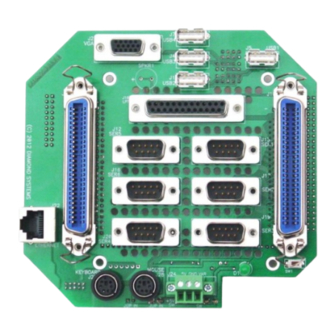
Page 5: Mechanical Drawing
MECHANICAL DRAWING A mechanical drawing of the Athena III panel I/O board connector layout is provided below. The drawing shows the top side of the panel I/O board with the relative connector locations. All I/O connectors are located on the board so that there is sufficient room to install all connectors without interference with any other connector or mounting hole. -
Page 6: Functional Description
The 5VDC output of this DC/DC power supply then has two paths to the Athena III SBC: (1) It can connect directly to the PC/104 bus of the system, if the power supply is mounted on the bus;... -
Page 7: Sbc I/O Section - Bottom Side
5.2 Input Power The power signals on these connectors come from either the front panel input power connector via jumpers, or an external switch, and connect to the power signals on the PC/104 connector of the Athena III SBC. +12V 5.3 VGA... -
Page 8: Serial Ports
5.4 Serial Ports This connector provides 4 serial ports, printer port and PS/2 keyboard and mouse signals from the Athena III CPU board. The four serial ports are jumper-configurable for RS-232, RS-422, or RS-485 protocols. SERA DCD PPRT_~STRB SERA DSR... -
Page 9: Usb 0/1 Ports
Shield / Ground USB3 Pwr- USB2 Pwr- USB3 Data+ USB2 Data+ USB3 Data- USB2 Data- USB3 Pwr+ USB2 Pwr+ www.diamondsystems.com Page Athena III Panel I/O Board User Manual Rev A... -
Page 10: Data Acquisition I/O
5.7 Data Acquisition I/O This connector provides a connection for the DAQ functions on the Athena III SBC. DIO A0 DIO A1 DIO A2 DIO A3 DIO A4 DIO A5 DIO A6 DIO A7 DIO B0 DIO B1 DIO B2... -
Page 11: Sbc I/O Section - Top Side
Athena III SBC power connector via an external power switch. If there is +12V available with the +5V then there is an option to jumper the +12V to the +12V bus on the Athena III SBC power connector. -
Page 12: Serial Ports
DCD 1 DSR 1 RXD 1 RTS 1 TXD 1 CTS 1 DTR 1 RI 1 GND 1 RS-232 Configuration RS-422 Configuration RS-485 configuration TXD+ TXD- TXD/RXD+ TXD/RXD- RXD- RXD+ www.diamondsystems.com Page Athena III Panel I/O Board User Manual Rev A... -
Page 13: Expansion I/O Section
These connectors are on the bottom side of the panel I/O board, outside the PC/104 outline. They do not connect to the Athena III SBC. They are used for other internal connections and functions. These connectors are 0.1” pitch male pin headers. -
Page 14: Power Section
The +12V input option jumper is also a 0-ohm ¼ watt T/H resistor used to route +12V from the Vin pin to the +12V pin on the Athena III power connector. If the Vin voltage is not +12V then the resistor is cut away to isolate the +12V pin on the Athena III primary power connector.
Need help?
Do you have a question about the ATHENA III and is the answer not in the manual?
Questions and answers