Table of Contents
Advertisement
Quick Links
SATURN
PCIe/104 Expandable Single Board Computer
with Intel "Apollo Lake" E3940 Processor
Revision
Date
Comment
1.01
09/13/2021
Initial Release
FOR TECHNICAL SUPPORT
Copyright 2021
PLEASE CONTACT:
Diamond Systems Corporation
www.diamondsystems.com
support@diamondsystems.com
Saturn User Manual V1.01
www.diamondsystems.com
Page 1
Advertisement
Table of Contents

Related Manuals for Diamond Systems SATURN SAT-E3940-4GA

Summary of Contents for Diamond Systems SATURN SAT-E3940-4GA
- Page 1 SATURN PCIe/104 Expandable Single Board Computer with Intel “Apollo Lake” E3940 Processor Revision Date Comment 1.01 09/13/2021 Initial Release FOR TECHNICAL SUPPORT Copyright 2021 PLEASE CONTACT: Diamond Systems Corporation www.diamondsystems.com support@diamondsystems.com Saturn User Manual V1.01 www.diamondsystems.com Page 1...
-
Page 2: Table Of Contents
CONTENTS Important Safe Handling Information ......................4 Introduction ..............................6 Models ................................6 Features ................................ 6 Operating System Support ........................... 7 Mechanical, Electrical, Environmental ......................7 Functional Overview ............................8 Block Diagram .............................. 8 Feature Descriptions ............................ 9 3.2.1 Processor and Chipset ......................... 9 3.2.2 Memory .............................. - Page 3 Restoring Default BIOS Settings ........................ 33 Upgrading BIOS using SHELL Utility......................33 Setting the Date and Time .......................... 33 Boot Priority ..............................34 LED ................................34 Quiet / Quick Boot / Splash Screen ......................34 Serial Port Configuration ..........................34 10 Getting Started ...............................
-
Page 4: Important Safe Handling Information
The list here describes common causes of failure found on boards returned to Diamond Systems for repair. This information is provided as a source of advice to help you prevent damaging your Diamond (or any vendor’s) embedded computer boards. - Page 5 Overvoltage on analog input – If a voltage applied to an analog input exceeds the design specification of the board, the input multiplexor and/or parts behind it can be damaged. Most of our boards will withstand an erroneous connection of up to 35V on the analog inputs, even when the board is powered off, but not all boards, and not in all conditions.
-
Page 6: Introduction
2 INTRODUCTION SATURN is a 4.5” x 4.0” PCIe/104-expandable SBC based on Intel Apollo lake x5-E3940 processor with a PassMark rating of approximately 1900. The board provides expansion option over minicard and PCIe/104 OneBank. It features 4GB Non-ECC/ 8GB ECC DDR3L memory soldered on board, conduction cooling, Minicard socket, M.2 socket, two Gigabit Ethernets, multiple displays and -40 to +85C operation. -
Page 7: Operating System Support
1 port with RS232 capability Data Acquisition 16 16-bit analog inputs with 250KHz maximum sample rate 4 16-bit analog outputs with waveform generator 22 digital I/O lines with programmable direction (16 DIO on N models) 8 32-bit counter/timers 4 24-bit PWMs ... -
Page 8: Functional Overview
3 FUNCTIONAL OVERVIEW 3.1 Block Diagram Block Diagram Saturn User Manual V1 www.diamondsystems.com Page 8... -
Page 9: Feature Descriptions
3.2 Feature Descriptions This section describes the key subsystems of the Saturn SBC. 3.2.1 Processor and Chipset The Intel Atom® processor E390x series, formerly Apollo Lake, empowers real-time computing in digital surveillance, new in-vehicle experiences, advancements in industrial and office automation, new solutions for retail and medical, and more. -
Page 10: Minicard Socket
3.2.7 Minicard Socket The board provides expansion for one full size (51mm length) Minicard socket. The socket supports mPCIe add on cards. Minicard interface support PCIex1 lane port and one USB2.0 port. Access to sim card signals are not provided. If LTE modem need to be used, please select module with SIM connector. SBC provides 2nos onboard M2 3.55mm spacer and M2 screws to mount minicard module 3.2.8 The board offers seven USB 2.0 ports and two USB 3.0 ports directly from the processor. -
Page 11: Rtc Backup Battery
3.2.11 RTC Backup Battery The RTC current consumption is 6uA with RTC voltage at 3.0V while the system is in a mechanical off (G3) state at room temperature. This data can be used to estimate the battery life. The voltage of the battery can affect the RTC accuracy. -
Page 12: Utility
3.2.15 Utility The board offers two 2x5 utility connectors, one with LPC bus interfaces for external IO expansion and another with Serial Port (RS232), Power Button, Reset button and I2C interface. Out of the two connectors, one provides 500mA fused 3.3V and 5V and the other connector provide 500mA fused 3.3V. -
Page 13: Power Supply
3.2.18 Power Supply The board requires only +5VDC input voltage as per the PCIe/104 Specification. It supports ACPI for pushbutton on/off control. It supports Standby mode with an optional +5VSB input. In standby mode, the board may be powered on via Wake on Lan feature on at least one Ethernet port. The 5V supply on the PCIe/104 connectors is routed directly to the input power connector, so that the board may obtain its input power from either the input power connector or from the bus connector. -
Page 14: Rugged Design
3.3 Rugged Design Saturn is designed from the ground up with a comprehensive set of features to meet the challenges of rugged environments and applications: Memory is soldered down to avoid problems that can occur with commercial style SODIMM type memory modules ... -
Page 15: Board Mechanical Drawing
4 BOARD MECHANICAL DRAWING Dimensions are in inches [mm]. Connector dimensions indicate the center of the pad for pin 1. Mechanical Drawing Saturn User Manual V1 www.diamondsystems.com Page 15... -
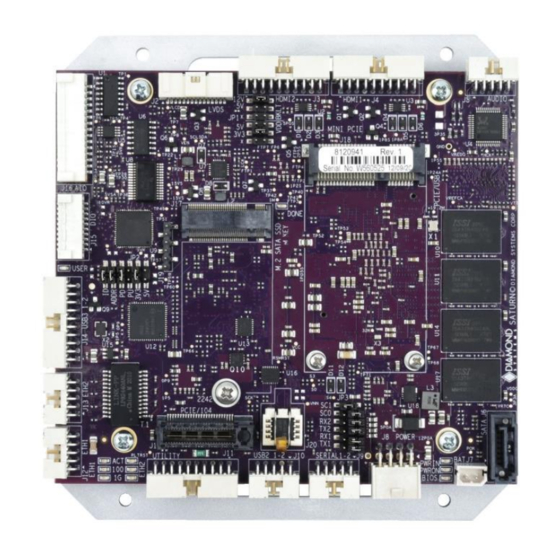
Page 16: Connector And Jumper Locations
5 CONNECTOR AND JUMPER LOCATIONS Board layout – Top Saturn User Manual V1.01 www.diamondsystems.com Page 16... - Page 17 Board layout – Bottom Saturn User Manual V1 www.diamondsystems.com Page 17...
- Page 18 I/O Connectors, Jumpers and LED Summary Connec Function Jumper Function PCIe/104 One LVDS Vcc & Backlight Voltage Selection bank Digital IO voltage and pull resistors, FPGA LVDS LCD Address Serial Port protocol Termination HDMI2 selection HDMI1 LED Block 1 (ETH1) Audio Top LED GBE0 ACT...
-
Page 19: O Connectors
6 I/O CONNECTORS 6.1 Connector Pin-out and Signal Description 6.1.1 Power In (J8) Input power may be supplied through the connector J8. All the required supply voltages for the board are derived from the 5V input. The +12V input is optional and necessary only to drive LCD backlight. Ground +12V(Optional) Ground... -
Page 20: Usb 2.0 Ports (J10)
Serial ports 1 and 2 are provided on a connector which can be configurable for RS-232, RS-422, or RS-485 Modes. The pinouts of the connector are as below: RS-232 RTS1 CTS1 RTS2 CTS2 RS-422 TX1+ TX1- RX1+ RX1- TX2+ TX2- RX2+ RX2- RS-485... -
Page 21: Lpc & Utility (J11, J12)
6.1.5 LPC & Utility (J11, J12) The utility connector provides access to power button, reset signal, I2C port, Serial Port and LPC signals. It provides fused 3.3V and 5V power that can be used for powering customer auxiliary circuitry. The pinouts of the Utility and LPC connectors are below: RS232 TXD I2C Clock RS232 RXD... -
Page 22: Sata (J6)
6.1.8 SATA (J6) The board provides access to SATA interface through a standard 7-pin connector. The pinout of this connector is as below: Ground SATA TX+ SATA TX- Ground SATA RX- SATA RX+ Ground Connector Type: 7-position vertical through connector, Molex# 0678008025. Mating Cable: Standard HDMI cable 6.1.9 Audio (J5) -
Page 23: Lcd Backlight (J24)
6.1.11 LCD Backlight (J24) The brightness control for the LCD backlight has a weak pull-down resistor to ensure maximum brightness when it is not connected externally. This signal may be controlled by a PWM pin from the processor. A jumper selects the source of the brightness signal to this pin. -
Page 24: Hdmi (J3, J4)
6.1.12 HDMI (J3, J4) The board provides access to two HDMI ports on two identical connectors. The pinout is shown below: Data 2+ Data 2- Data 1+ Data 1- Data 0+ Data 0- Clock+ Ground Clock- CEC (NC) Reserved DDC Clock DDC Data Hot Plug Detect Chassis ground... -
Page 25: Minicard Socket (J20)
6.1.15 MiniCard Socket (J20) The board provides access to PCIe mini card interface via Mini card socket. For the connector shown below, all TX/RX signals are with respect to the host. TX on the socket drives RX on the installed module, and RX on the socket is driven by TX on the installed module. -
Page 26: Sata Socket (J19)
6.1.17 M.2 SATA Socket (J19) The board provides mass storage support via an M.2 socket that supports SATA modules of size 2242. For the pinouts shown, all TX/RX signals are with respect to the host. TX on the socket drives RX on the installed module, and RX on the socket is driven by TX on the installed module. -
Page 27: Pcie/104 (J1)
6.1.19 PCIe/104 (J1) The board provides expansion to PCIe/104 via a One-Bank connector. The connector provides access to four x1 PCIe lanes, two USB2.0s, ATX power & control signals, +3.3V & +5V power rails and SMBus interfaces. The pinout of the connector is shown below: USB-OC# PCIe Reset# +3.3V... -
Page 28: List Of Connectors
6.2 List of Connectors The following table provides a summary of all I/O connectors on the board. Function Manufacturer Part no. Description Mating part Mating Cable Power in Samtec ASP-194529-01 2x4 box header T/H Right IPD1-04-D-K 6980512 angle .1” pitch External Molex 22-05-7025... -
Page 29: O Cables
7 I/O CABLES Photo No: Cable Part No Description Saturn Connector 6980512 Power in 6980524 External Battery 6980601 Serial Port 6980602 USB2.0 6980603 USB3.0 J15, J16 6980604 Ethernet J13, J14 6980605 HDMI J3, J4 6980608 Audio 6989101 SATA 6980517 Digital I/O 6980518 Analog I/O 6980609... -
Page 30: Jumper Description
8 JUMPER DESCRIPTION Following drawing shows only the connectors and jumper blocks on the board. The default jumper positions are shown in blue. Default Jumper locations Jumper Description LVDS LCD VCC and Backlight DIO PU/PD, Voltage, Address Serial Port protocol and termination Saturn User Manual V1.01 www.diamondsystems.com Page 30... -
Page 31: Lvds Backlight And Lvds Vdd (Jp1)
8.1 LVDS Backlight and LVDS VDD (JP1) Jumper block JP1 configures the voltage supply for the LCD backlight and LVDS VDD. By default, LVDS backlight is provided with +12V and the LVDS VDD is provided with 3.3V. Position Function LCD Backlight Voltage 12V* LCD Backlight Voltage LCD VDD Voltage... - Page 32 Serial port Mode selection Jumper (Detailed): Protocol Internal Loopback RS485 RS232 RS422 Saturn User Manual V1 www.diamondsystems.com Page 32...
-
Page 33: Bios Key Features (Tbu)
9 BIOS KEY FEATURES (TBU) The BIOS on Saturn provides access to many valuable features. These instructions show how to enter the BIOS and set up features. 9.1 Entering the BIOS The BIOS may be entered during startup by pressing the DEL key on an attached keyboard. Press the key repeatedly soon after a power-on or reset until the BIOS screen appears. -
Page 34: Boot Priority
9.5 Boot Priority To select Boot devices and priority, go to the Boot menu and select Boot Device Priority. Only devices which are connected to the board will appear in the list of options. Therefore, if the user wants to select a hard drive or USB device as the boot device, CPU should be connected first, then boot up and enter the BIOS, then select it as a boot device. -
Page 35: Getting Started
10 GETTING STARTED This section describes the steps needed to get Saturn SBC up and running and assumes that user also has a Saturn Development Kit or Saturn Cable Kit. The Cable Kit includes all cables needed for the I/O, except the LCD and backlight. -
Page 36: Installing Os And Booting
10.3 Installing OS and Booting Ensure that SATA data cable and power cable are connected to SATA HDD. Follow below steps to install Windows 10 operating system in SATA HDD. Connect a USB pen drive to a USB port of (J15/J16) Saturn board having Windows 10 installation image. ... -
Page 37: Video Features
11 VIDEO FEATURES Saturn SBC offers three video output options: 2 DDI and one eDP. The DDI ports are configurable for either HDMI 1.4, DP 1.1a, or eDP. All the three outputs can be active at any time. DDI port 1 is configured as HDMI 1.4 and supports a maximum resolution of 1920 x 1080 x 60Hz x 24bpp. DDI port 2 is used for VGA and VGA is realized using DP to VGA converter. -
Page 38: Serial Ports And System Console
12 SERIAL PORTS AND SYSTEM CONSOLE 12.1 Configuration Saturn SBC supports total 4 serial ports. All the 4 ports support RS-232/422/485 modes. The modes can be configured in BIOS. Both TX and RX termination selection option are available under BIOS menu. 12.2 Console redirection Connect any of the Saturn serial ports to PC. -
Page 39: Data Acquisition Circuit
13 DATA ACQUISITION CIRCUIT 13.1 Overview Saturn contains a data acquisition subsystem consisting of A/D, D/A, digital I/O, and counter/timer features. The circuit is controlled by an FPGA and connected to the SBC via the LPC bus. The A/D section includes a 16-bit A/D converter, 16 analog input channels and a 2048-sample FIFO. Input ranges are programmable, and the maximum sampling rate is 250 KHz. -
Page 40: Software Driver Overview
SATA DOM installed with either Windows 10 or Linux. All the necessary I/O drivers are also available as part of the Development Kit. Please contact Diamond Systems for more details. Some of the drivers that are required with the Windows 10 operating system are given below. These drivers are available for download from Diamond Systems’... -
Page 41: Thermal Solution
15 THERMAL SOLUTION Saturn integrates a heat spreader mounted on the bottom side of the board. The heat spreader is intended for installation onto a metal enclosure surface to aid in conducting heat away from the processor and dissipating it through the enclosure body. -
Page 42: Specifications
16 SPECIFICATIONS Item SAT-E3940-4GA SAT-E3940-4GD SAT-E3940-8GEA SAT-E3940-8GED Processor Apollo Lake E3940 Apollo Lake E3940 Apollo Lake E3940 Apollo Lake E3940 Speed 1.6GHz 1.6GHz 1.6GHz 1.6GHz SDRAM 4GB Non ECC 4GB Non ECC 8GB ECC 8GB ECC memory AIO + DIO AIO + DIO Cooling Heat Spreader...
Need help?
Do you have a question about the SATURN SAT-E3940-4GA and is the answer not in the manual?
Questions and answers