Sign In
Upload
Download
Table of Contents
Contents
Add to my manuals
Delete from my manuals
Share
URL of this page:
HTML Link:
Bookmark this page
Add
Manual will be automatically added to "My Manuals"
Print this page
×
Bookmark added
×
Added to my manuals
Manuals
Brands
Atlas Copco Manuals
Water Pump
CLAWVAC CP65
Original operating instructions
Atlas Copco CLAWVAC CP65 Original Operating Instructions
Dry claw vacuum & overpressure pumps
Hide thumbs
1
2
Table Of Contents
3
4
5
6
7
8
9
10
11
12
13
14
15
16
17
18
19
20
21
22
23
24
25
26
27
28
29
30
31
32
33
34
35
36
37
38
39
40
41
42
43
44
45
46
47
48
49
50
51
52
53
54
page
of
54
Go
/
54
Contents
Table of Contents
Bookmarks
Table of Contents
Table of Contents
Safety Precautions
Safety Icons
Safety Precautions, General
Safety Precautions During Installation
Safety Precautions During Operation
Safety Precautions During Maintenance or Repair
General Description
What Is Vacuum and How Is Flow Rate Understood
Introduction
Figure 1 - CP65, CP150, CP300 Dry Claw Vacuum Pumps Back View
Figure 2 - CP65, CP150, CP300 Dry Claw Vacuum Pumps Front View
Figure 3 - OP150, OP300 Dry Claw Overpressure Pumps Back View
Figure 4 - OP150, OP300 Dry Claw Overpressure Pumps Front View
Flow Diagram
Figure 5 - Flow Diagram - CP65, CP150, CP300 Dry Claw Vacuum Pumps
Figure 6 - Flow Diagram - OP150, OP300 Dry Claw Overpressure Pumps
Figure 7 - Pump Cooling
Condensate System
Figure 8 - Position of Drain Port
Installation
Dimension Drawings
Figure 9 - Dimension Drawing, CP65, CP150
Figure 10 - Dimension Drawing, CP300
Figure 11 - Dimension Drawing, OP150
Figure 12 - Dimension Drawing, OP300
Table 1 - Dimensions and Weight
Installation Proposal
Figure 13 - Installation Proposal, CP65, CP150, CP300 Dry Claw Vacuum Pumps
Figure 14 - Installation Proposal, OP150, OP300 Dry Claw Overpressure Pumps
3.3 Electrical Connections
Pictographs
Figure 15 - Pictographs and Labels
Operating Instructions
Initial Start-Up
Starting
During Operation
Stopping
Taking out of Operation
Maintenance
Preventive Maintenance Schedule
Table 2 - Preventive Maintenance Schedule
Oil Specifications
Storage
Disposal of Used Material
Adjustments and Servicing Procedures
Air Filter
Oil Top-Up
Cleaning Motor Fan and Vent Holes
Problem Solving
Table 3 - Faults and Remedies
Technical Data
Reference Conditions and Limitations
Pump Data
Table 4 - Reference Conditions
Table 5 - Limitations
Table 6 - Common Pump Data
Motor Data
Table 7 - Motor Data
Electric Cable Size and Fuses
Table 8 - Currents and Fuses
Instructions for Use
Declaration of Conformity
Advertisement
Quick Links
1
Maintenance
Download this manual
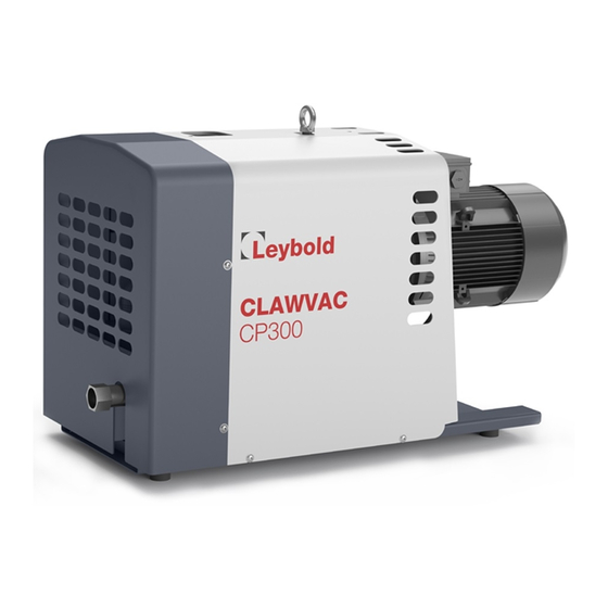
CLAWVAC
CP65 - CP150 - CP300 - OP150 - OP300
Dry claw vacuum & overpressure pumps
Original Operating Instructions 300676782_002_C0
Part Numbers :
178065 V01 / 10
178150 V01 /10
178300 V01 / 10
178150 P01 / 10
178300 P01 / 10
6996 0229 87 Issue A – 05/2017 – © Leybold
Table of
Contents
Previous
Page
Next
Page
1
2
3
4
5
Advertisement
Table of Contents
Need help?
Do you have a question about the CLAWVAC CP65 and is the answer not in the manual?
Ask a question
Questions and answers
Related Manuals for Atlas Copco CLAWVAC CP65
Water Pump Atlas Copco CLAWVAC CP150 Original Operating Instructions
Dry claw vacuum & overpressure pumps (54 pages)
Water Pump Atlas Copco CLAWVAC CP300 Original Operating Instructions
Dry claw vacuum & overpressure pumps (54 pages)
Water Pump Atlas Copco WEDA 30 Instruction Manual
(28 pages)
Water Pump Atlas Copco GHS VSD+ Series Instruction Manual
Oil-sealed rotary screw vacuum pumps (144 pages)
Water Pump Atlas Copco DZS 065V Instruction Book
Dry claw vacuum & overpressure pumps (56 pages)
Water Pump Atlas Copco GHS 350 VSD+ Instruction Book
Oil-sealed rotary screw vacuum pumps (124 pages)
Water Pump Atlas Copco DWS VSD+ Instruction Manual
Dry screw vacuum pump (137 pages)
Water Pump Atlas Copco LRP 700 VSD+ Instruction Book
Intelligent liquid ring vacuum pumps (124 pages)
Water Pump Atlas Copco PAS Series Instruction Manual
(88 pages)
Water Pump Atlas Copco GHS 3800 VSD+ Instruction Book
Oil-sealed rotary screw vacuum pumps (132 pages)
Water Pump Atlas Copco WEDA 50 Instruction Manual
(28 pages)
Water Pump Atlas Copco GVS 16A Instruction Book
Oil-sealed rotary vane vacuum pumps (77 pages)
Water Pump Atlas Copco GHS 350 VSD+ Instruction Manual
Oil-sealed rotary screw vacuum pumps (116 pages)
Water Pump Atlas Copco PAS Series Instruction Manual
(70 pages)
Water Pump Atlas Copco WEDA 04 Instruction Manual
Weda dewatering pump (28 pages)
Water Pump Atlas Copco GVS 16A Instruction Manual
Oil-sealed rotary vane vacuum pumps (84 pages)
This manual is also suitable for:
Clawvac cp150
Clawvac cp300
Clawvac op150
Clawvac op300
Table of Contents
Print
Rename the bookmark
Delete bookmark?
Delete from my manuals?
Login
Sign In
OR
Sign in with Facebook
Sign in with Google
Upload manual
Upload from disk
Upload from URL


Need help?
Do you have a question about the CLAWVAC CP65 and is the answer not in the manual?
Questions and answers