Rose electronics RP2-1R2X16U Installation And Operation Manual
Ultramatrix remote series kvm matrix switch with remote access
Hide thumbs
Also See for RP2-1R2X16U:
- Product overview (12 pages) ,
- Overview (19 pages) ,
- Specifications (2 pages)

Related Manuals for Rose electronics RP2-1R2X16U


Summary of Contents for Rose electronics RP2-1R2X16U
- Page 1 UltraMatrix Remote INSTALLATION AND OPERATIONS 10707 Stancliff Road Houston, Texas 77099 ™ KVM MATRIX SWITCH WITH REMOTE ACCESS MANUAL Phone (281) 933-7673 www.rose.com...
-
Page 2: Limited Warranty
Rose Electronics warrants the UltraMatrix™ Remote to be in good working order for one year from the date of purchase from Rose Electronics or an authorized dealer. Should this product fail to be in good working order at any time during this one-year warranty period, Rose Electronics will, at its option, repair or replace the Unit as set forth below. - Page 3 FCC/IC STATEMENTS, EU DECLARATON OF CONFORMITY FEDERAL COMMUNICATIONS COMMISSION AND INDUSTRY CANADA RADIO-FREQUENCY INTERFERENCE STATEMENTS This equipment generates, uses, and can radiate radio frequency energy and if not installed and used properly, that is, in strict accordance with the manufacturer’s instructions, may cause interference to radio communication. It has been tested and found to comply with the limits for a Class B digital device in accordance with the specifications of Part 15 of FCC rules, which are designed to provide reasonable protection against such interference when the equipment is operated in a commercial environment.
-
Page 4: Table Of Contents
Upgradeability...2 Security ...2 Flexibility ...2 On-screen display technology...2 Compatibility...2 Cable requirements ...3 Package contents ...3 Rose Electronics web site...3 UltraMatrix Remote Models ...4 Rear Panel ...4 System overview...5 UltraMatrix Remote Installation...6 Connecting the hardware ...6 Connecting the KVM station ...6 Connecting to the network ...6... - Page 5 Logout ... 20 Configure group menu... 21 System Status display ... 23 Computers... 23 Power ... 23 Pos (Position) ... 23 Ver (Version) ... 23 KVM ... 23 CPU ... 23 User ... 23 Status... 23 Save menu... 24 Connecting the expansion units... 28 Serial port usage (RS232)...
- Page 6 Figures Figure 1. Typical Application...5 Figure 2. Quad screen mode ...5 Figure 3. Configure Login screen...7 Figure 4. Network configure login screen...8 Figure 5. Main menu ... 10 Figure 6. Configure system menu... 11 Figure 7. Configure computer menu ... 14 Figure 8.
-
Page 7: Disclaimer
Rose Electronics UltraMatrix Remote switches are designed to meet your switching needs, whatever your system demands are, one user of multiple users, one computer or hundreds. All models offer standard features that allow for easy, secure, and complete access to as many as 1,000 computers from one or multiple KVM stations. -
Page 8: Features
Solid state embedded unit has no disk drive for maximum reliability Upgradeability Free lifetime base firmware upgrades, based on flash memory technology provide new features and improvements. Base firmware upgrades are available from our web site at www.rose.com. Security Security system with login requirements, computer access control and data encryption... -
Page 9: Cable Requirements
CPU cable for each computer connected to the UltraMatrix Remote, expansion cables if the system is expanded in a BUS or RING configuration, and a cable to connect the unit your network. Rose Electronics offers a wide variety of cable types to directly connect your PC’s, Sun systems, MAC computers and others. See Appendix B for cable part numbers. -
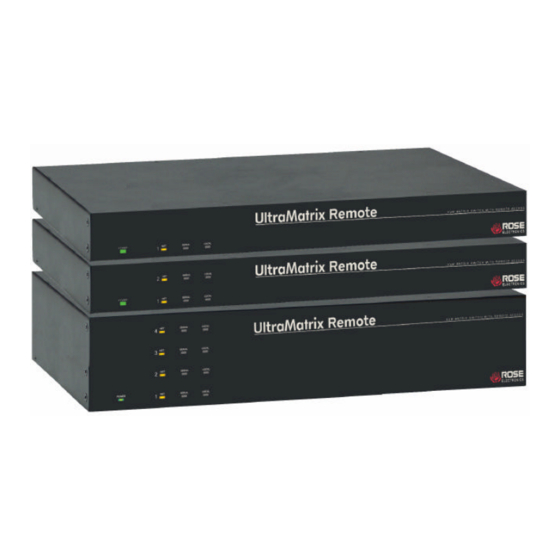
Page 10: Ultramatrix Remote Models
Models UltraMatrix Remote Models 1 x 8 (Model number RP2-1R1X8U/E1) 2 x 8 (Model number RP2-2R2X8U/E1) 4 x 16 (Model number RP4-4R8X16U/E2) Connector Power Connector IEC320 Expansion card(s) Connectors DB15M (Output) DB15F (Input) CPU Connector DB25F ULTRAMATRIX REMOTE INSTALLATION AND OPERATIONS MANUAL Rear Panel Description Connector... -
Page 11: System Overview
The Versatility and flexibility of the UltraMatrix Remote gives you the capability of expanding the number of computers/servers that can be accessed to 1,000. The expansion can be done by adding additional UltraMatrix Remote units or other Rose Electronics KVM switches UltraMatrix Remote... -
Page 12: Ultramatrix Remote Installation
Installation UltraMatrix Remote Installation The installation of the UltraMatrix Remote consists of three procedures; connecting the hardware, configuring the unit, installing and connecting the computers, and installing the viewer. The on-screen display (OSD) and the set-up wizard will guide you through the installation and configuration procedures for the unit and remote viewer. Connecting the hardware Connecting the KVM station Connect a local KVM station to the... -
Page 13: Configuring The Unit
UltraMatrix Remote and are not routed through the remote access hardware. These ports will not require a login name and password unless security on the UltraMatrix Remote is configured to require a login. ULTRAMATRIX REMOTE INSTALLATION AND OPERATIONS MANUAL Copyright 2003 Rose Electronics F10 - Configure KVM 2 (local access only) no login required unless configured... -
Page 14: Figure 4. Network Configure Login Screen
NOTE: The switch configuration can be performed locally or through the viewer on a network workstation. ULTRAMATRIX REMOTE INSTALLATION AND OPERATIONS MANUAL Copyright 2003 Rose Electronics IP address, subnet mask and gateway Are the standard TCP/IP settings. They become effective immediately Upon save and exit. -
Page 15: System Configuration Menus
Menu structure To display the main KVM switch configuration menu, from the “Connect Login” screen, enter the User ID of “admin” and no password and press enter. The screen will go blank waiting for a command. Press and release the left control key, then press the F12 key to display the switch configuration menu. -
Page 16: Main Menu
Main Menu (Pressing the left control key, then F12 displays the main menu) UltraMatrix version MX21C Rose Electronics Main Menu Configure System Computer User Profile Group Language Status Save Exit Use up/down arrow keys To choose selection then press the Enter key... -
Page 17: Configure System Menu
Configure System menu Configure system System settings Configure password Starting computer number Maximum computers Keyboard settings PC keyboard rate (chars/sec) PC keyboard delay Sun keyboard language Appearance Menu color scheme Screen saver Screen saver time (seconds) Background color Text color Position Fadeout (seconds) Password to configure unit... -
Page 18: Maximum Computers
Maximum computers (Default: 64) The “Maximum computers” value is calculated by multiplying the number of RS232 ports on all switches by 4. This value must be entered from KVM station #1 before all Units are connected in an expansion topology. When saved, this value is propagated to all connected Units. -
Page 19: Screen Saver Time (Seconds)
Screen saver time (seconds) (Default: 1800 seconds) Determines the period of keyboard or mouse inactivity before activating the screen saver. To change the screen saver time, select it from the menu and press [Enter]. An input box will display to enter a new screen saver time. Enter a new value from 0 to 9999 seconds and press [Enter]. -
Page 20: Configure Computer Menu
Configure Computer menu Configure computer Computer name ekeyboard Computer 2 Computer 2 PC2 3 Computer 3 PC2 4 Computer 4 PC2 5 Computer 5 PC2 6 Computer 6 PC2 7 Computer 7 PC2 8 Computer 8 PC2 9 Computer 9 PC2 10 Computer 10 PC2 11 Computer... -
Page 21: Keyboard
Keyboard (Default: PC mode 2) To change the keyboard type for a selected computer or configure the CPU port for a serial device, use the up/down arrow keys to select the computer whose keyboard needs changing. Use the right arrow key to select the keyboard field and press [Enter]. -
Page 22: Configure Kvm Menu
Configure KVM menu Configure KVM KVM name KVM station 1 KVM station 2 KVM station 3 KVM station 4 Name of keyboard-video-mouse station (KVM) up to 16 characters Figure 8. Configure KVM menu Note: On the 2 user model, only KVMs 1 and 2 will display. On the 4 user model, KVMs 1, 2, 3 and 4 will display. -
Page 23: Start
Start (Default: 0) Assigns the CPU port number the KVM station will connect to on start up and login. 0 = no connection. To change the value, select it from the menu and press [Enter]. Type in the CPU port number the selected KVM station will connect to upon start up or login and press [Enter]. -
Page 24: Configure User Menu
The configure user, profile, and group features provide a flexible and reliable security set-up for your system. Configure User menu Configure User User name Password User 1 * * * * * * * * User 2 * * * * * * * * User 3 * * * * * * * * User 4... -
Page 25: Configure Profile Menu
Configure profile menu Configure Profile Name Access Mode Profil 1 Group 1 Share Profil 2 Group 2 Share Profil 3 Group 3 Share Profil 4 Group 4 Share Profil 5 Group 5 Share Profil 6 Group 6 Share Profil 7 Group 7 Share Profil 8... -
Page 26: Share
Share (Default: 2 seconds) This feature allows other users to take keyboard and mouse control of a computer after a specific time of no keyboard or mouse activity by a user. To change the Share time for a given profile, select the profile, then the Share to change and press [Enter]. -
Page 27: Configure Group Menu
Configure group menu Configure Group Computer 1 Computer + + + + + + + + + + + + + + + + 2 Computer + + + + + + + + + + + + + + + + + 3 Computer + + + + + + + + + + + + + + + + + 4 Computer... -
Page 28: Configure Language
Configure Language UltraMatrix version MX21C Rose Electronics Copyright 1990-2002 Main Menu Configure System Computer User Profile Group Language Status Save Exit Use up/down arrow keys To choose selection then press the Enter key Or the Escape key to exit Configure password, box number, Figure 12. -
Page 29: System Status Display
System Status display System Status Computer Power Pos 1 21C 2 21C 9-12 3 21C 13-16 4 21C 17-20 1 21C 21-24 2 21C 25-28 3 21C 29-32 4 21C 33-36 1 21C 37-40 2 21C 41-44 3 21C 45-48 4 21C 49-52 1 21C... -
Page 30: Save Menu
Save menu UltraMatrix version MX21C Rose Electronics Copyright 1990-2002 Main Menu Configure System Computer User Save configuration? Profile Group Language Status Save Exit Use up/down arrow keys to choose selection then press the Enter key or the Escape key to exit Configure password, box number, keyboards settings, appearance Figure 14. -
Page 31: Switch Installation - Single Unit
Switch Installation Switch Installation – Single Unit Please refer to the safety section before installation The basic installation of a single UltraMatrix Remote is an easy and straightforward procedure. Perform the below steps for all computers that will be connected. It is recommended that all computers be powered off. When a computer is connected and then booted, the UltraMatrix Remote will automatically determine the keyboard and mouse types used for that computer and no pre-configuration is needed. - Page 32 Perform the following installation steps for each computer that will be connected to the UltraMatrix Remote. Sequentially connect the computers starting with computer #1. STEPS: (Refer to the troubleshooting section for help if needed) 1. Connect a KVM station to the UltraMatrix Remotes DB25F, KVM #1 connector using the appropriate KVM cables. 2.
-
Page 33: Switch Installation - Multiple Units - "Bus" Topology
The connection to the network can be done at this time but it is not necessary to install multiple units. Figure 15. Bus installation The Units can be any UltraMatrix Remote model or other Rose Electronics KVM switches Upper expansion card and cabling are on the 4 user model only. -
Page 34: Connecting The Expansion Units
To start, identify the following prior to installation: 1. Which UltraMatrix Remote will be #1, #2, and so on. 2. Which computer will be #1, #2, and so on. 3. Which computers do not use a PC2 keyboard or a PS/2 mouse. 4. - Page 35 Select “Status” from the Main menu and press [Enter]. The system status screen will display showing the following ( 6. Figure 13) a. Computers b. Power (Power on status) c. POS (Card position) d. VER (Program version) e. KVM f. CPU g.
- Page 36 17. Verify that the keyboard, video, and mouse on the connected computer function properly before proceeding. 18. Switch the KVM station to the next sequential CPU port as explained in step 14 and perform steps 15 - 17 for this computer and for the remaining computers.
-
Page 37: Switch Installation - Multiple Units - "Ring" Topology
Switch Installation – Multiple units – “RING” topology A “RING” configuration is usually used when the users are connected to different UltraMatrix Remotes and need access to all computers. In a “RING” configuration, users on any KVM station in the ring can access all the computers in the system on a first-come-first-serve basis. - Page 38 To begin setting up your system in a “RING” configuration, perform steps 1 – 13 as outlined in setting up a “BUS” configuration. When doing this, keep in mind that the “OUT” expansion card connector on the first Unit will be connected with an expansion cable to the “IN”...
-
Page 39: Serial Port Usage (Rs232)
A serial cable (RJ12, 6-wire connector and an appropriate adapter for the computer's serial port). The serial cable and adapter are provided with each switch (Rose part number KIT-ATRX) n A dedicated computer, Notebook computer with a serial port, or a display terminal. Using a display terminal will allow you to configure the UltraMatrix switch, however, you will not be able to upgrade new versions of firmware. -
Page 40: Serial Menu Options
Option 3. Receive new main program or kernel from serial port (This card only) When new main or kernel programs are available, they can be obtained from Rose Electronics or downloaded from our web site at www.rose.com. The diagnostic screen that is displayed when the UltraMatrix Remote is first turned on shows the Kernel and main program version that is presently installed. - Page 41 It is recommended that this procedure be done on Unit #1, RS232 port #1. (Lower right RJ12 connector) To load a flash upgrade file, type 3 in the Enter choice field of the serial options menu. The following message will appear: Waiting for file...
-
Page 42: Switching Using The Serial Port
Option 6. Reset to Factory Defaults (This CPU card only) NOTE: Before resetting any CPU card to factory defaults, note the starting computer number listed on the Serial menu, Option 1. When resetting a CPU card to factory defaults, this number will be set to one (1) and must be changed back to the original value by using option 1 to change the starting computer number and then saved using option 7. -
Page 43: Serial Device Support
Serial Device Support Serial device support The serial feature is available on the multi-platform models. The serial feature allows you to connect a KVM station to a serial device such as the serial port on a Unix or Sun computer, a router or hub, or any compatible serial device. The serial device is connected to the DB25F CPU port on the UltraMatrix Remote with a serial cable (See Appendix B for serial cable part numbers). - Page 44 With the CPU port configured for serial support and the appropriate serial cable connected, the KVM station can access the connected serial device the same way you would access it using a computer terminal. When you switch to a CPU port that is configured for serial support, the powerful OSD will emulate a VT220 terminal. You can also use the KVM station in a standard TTY mode which will automatically scroll incoming data.
-
Page 45: Remote Viewer Installation
Viewer Installation Remote Viewer Installation Software Installation The Viewer software must be installed on a Windows based workstation connected to the network. The workstation should have the following minimum requirements: 133 MHz PC with Microsoft Windows 95 or above 32 Mb of system memory 4Mb of free disk space VGA display adapter and monitor, capable of 640 x 480 resolution Keyboard and mouse... -
Page 46: Pass-Through Mode
Please note the following important items concerning using the Viewer for the first time. Pass-through mode When logging in to the UltraMatrix Remote from the Viewer for the first time, use the default administrator account User ID “admin” and no password. Once logged in, the Viewer is in the “Pass-through” mode. In this mode, all keyboard and mouse activity is passed to the UltraMatrix Remote. -
Page 47: Figure 18. Connections Menu
The first item to change is the default account information. To perform this, Launch to viewer and click on “Settings”, “Connections…”. The Settings window will appear showing the default account information. Click on “Edit Location” and change the “Default” Location name for this Unit to a location name appropriate for your system. Click “OK” to change the location name. -
Page 48: Figure 19. Security
The location name shown in Figure 20 will list all Unit locations that have been added. If more that one location has been added, click on the down arrow to list the locations, select one to connect to, and then click on the “Connect to remote hardware”... -
Page 49: Configuring The Viewer For The Ultramatrix Remote Model
Change the User ID of “admin” to a new administrator User ID or a new user (16 characters max, case sensitive, duplicate names are not allowed) Type in a new password in the “Password” field (16 characters max, case sensitive, duplicate passwords are allowed but not recommended) Re-type the password in the “Confirm password”... -
Page 50: System Operation
OPERATIONS System Operation The system operation section describes how to start the Viewer program, remotely connect to an UltraMatrix Remote, login to the UltraMatrix Remote, and disconnect. Starting the Viewer program To start the Viewer program, double click on the Viewer icon on the desktop if it was installed during the Viewer installation or click on the UltraMatrix Remote Viewer icon in the startup menu. - Page 51 When the Viewer successfully connects to the selected locations UltraMatrix Remote, the User must login with a valid user ID and Password. Enter the User ID assigned and click on “OK”. The Password request box will display. Enter the assigned password and click on “OK”. There is a 45 second time limit for entering the User ID and Password.
-
Page 52: Figure 22. Switch Connection
When the connected computer’s video displays, the Viewer is in the Pass-through mode. The Green indicator in the lower left toolbar will be “ON” when the Viewer is in the Pass-through mode. All keyboard and mouse activity applies to the UltraMatrix Remote. The Viewer’s menus and toolbar are not available in the Pass-through mode. To regain control of your computer and gain access to the Viewer’s menu and toolbar, use one of the below escape methods: HotKey shortcut §... -
Page 53: View Modes
Figure 26. Quad screen mode View modes The Viewer can be configured to show the computer’s video at its clearest size. To change the view mode, select “View” from the menu. ULTRAMATRIX REMOTE INSTALLATION AND OPERATIONS MANUAL... -
Page 54: Scrolled View
Scrolled view The scrolled view displays the image from the remote computer with its original size. If the Viewer’s display area is smaller than the computer’s video, vertical and horizontal scroll bars are added. If the Viewer’s display area is larger than the computer’s video, the Viewer centers the computer’s video. -
Page 55: Toolbar
Toolbar When checked, the toolbar is visible, un-checked, the top toolbar is removed. Status Bar When checked, the status bar is visible, un-checked, the bottom status bar is removed. Auto Size Now Resize the display area to fit the image size. Full Screen Selecting “Full Screen”... -
Page 56: Other Menu Items
Other menu items File menu The File menu provides three options: Shortcuts menu ULTRAMATRIX REMOTE INSTALLATION AND OPERATIONS MANUAL Flash Update – See Appendix F Save Bitmap – Saves the Viewer’s image to a .BMP file Exit – Exits the Viewer Issue Remote Alt+Tab –... -
Page 57: Help
Help Help Topics – Invokes full online help. UltraLink Web Support – Opens a browser and links to the UltraLink support web site. Full Screen Warning – Enables or disables the full-screen warning dialog. Pass Through Warning – Enables or disables the Pass-through warning dialog. -
Page 58: Service Information
Technical Support hours are from: 8:00 am to 6:00 pm CST (USA), Monday through Friday. Please report any malfunctions in the operation of this Unit or any discrepancies in this manual to the Rose Electronics Technical Support Department. ULTRAMATRIX REMOTE INSTALLATION AND OPERATIONS MANUAL... - Page 59 SAFETY Safety This Unit has been tested for conformance to safety regulations and requirements, and has been certified for international use. Like all electronic equipment, the Unit should be used with care. To protect yourself from possible injury and to minimize the risk of damage to this Unit, read and follow these safety instructions. Risk of explosion can occur if the battery is replaced with an incorrect type.
-
Page 60: Safety And Emc Regulatory Statements
Safety and EMC Regulatory Statements Informations concernant la sécurité Symbole de référence à la documentation. Si le produit est marqué de ce symbole, reportez-vous à la documentation du produit afin d’obtenir des informations plus détaillées. WARNING Dans la documentation, un WARNING indique un danger susceptible d’entraîner des dommages corporels ou la mort. -
Page 61: Troubleshooting
In the Quad view, the connection status window is always present in all quadrants Configure the Rose KVM switch and change the system configuration, fadeout time to zero (disabled) Mouse does not move n The UltraMatrix turned off after or not attached when computer booted or application began using mouse. -
Page 62: Appendices
APPENDICES Appendix A – Specifications Dimensions Width 16.7 42.4 Weight 1 x 4 = 8 lbs. (3.6 kg) 2 x 8 = Power Auto Switching, 115-230 VAC, 50/60 Hz, 750 ma, 100 watts Connectors Power: IEC 320 standard receptacle Local KVM: Video - HD15F, Keyboard - MD6F, Mouse - MD6F Switch or computer: DB25 female Ethernet port: RJ45 Serial port: DB9 male... -
Page 63: Appendix C - Rackmount
Appendix C – RackMount The rack mount kit includes the following items: n Two black anodized mounting brackets n Four 6 - 32 x 3/8” flat head mounting screws To rack mount your UltraMatrix Remote, attach the two rack mounting brackets to yo/ur Unit with the short flange against the Unit using the four screws provided. -
Page 64: Appendix D - Keycodes
Appendix D – KeyCodes The Key Codes are pre-defined for all Rose Electronics KVM switches. The keyboard commands to switch to a CPU port must be specified in the Key Code column if the UltraMatrix Remote is connected to a Custom KVM switch. -
Page 65: Appendix F - Ultramatrix Remote Firmware Upgrade
Appendix F – UltraMatrix Remote firmware upgrade When updates and enhancements are made to the UltraMatrix Remote features, new firmware updates is made available from Rose Electronics’ web site at www.rose.com or from the Viewer, click on Help, then UltraLink web support. -
Page 66: Appendix H - Kvm Placement / Conflicts
Appendix H – KVM placement / conflicts In an expanded system with multiple UltraMatrix Remotes, no user conflicts will occur provided the KVM stations are on different KVM ports. That is one KVM station on KVM port #1, and one on KVM port #2 for the 2 usermodel;... - Page 68 10707 Stancliff Road Houston, Texas 77099 Phone (281) 933-7673 www.rose.com...
Need help?
Do you have a question about the RP2-1R2X16U and is the answer not in the manual?
Questions and answers