
Related Manuals for Rose electronics KVL-4PCA


Summary of Contents for Rose electronics KVL-4PCA
- Page 1 VISTA L-SERIES INSTALLATION AND OPERATIONS MANUAL 10707 Stancliff Road Phone: (281) 933-7673 Houston, Texas 77099 WWW.ROSE.COM...
-
Page 3: Limited Warranty
LIMITED WARRANTY Rose Electronics warrants the Vista™ to be in good working order for one year from the date of purchase from Rose Electronics or an authorized dealer. Should this product fail to be in good working order at any time during this one-year warranty period, Rose Electronics will, at its option, repair or replace the Unit as set forth below. -
Page 4: European Union Declaration Of Conformity
FCC/IC STATEMENTS, EU DECLARATION OF CONFORMITY FEDERAL COMMUNICATIONS COMMISSION AND INDUSTRY CANADA RADIO-FREQUENCY INTERFERENCE STATEMENTS This equipment generates, uses and can radiate radio frequency energy and if not installed and used properly, that is in strict accordance with the manufacturer’s instructions may cause interference to radio communication. -
Page 5: Table Of Contents
Optional on-screen display (OSD) features... 2 Compatibility ... 3 System overview ... 4 KVM station ... 4 CPU connections... 4 Rose Electronics web site ... 5 Vista L-Series models... 6 Vista cables ... 9 Installation... 10 Step 1 - Connecting the KVM station ... 10 Step 2 - Connect the CPUs ... - Page 6 Tables Table 1. Compatibility... 3 Table 2. Front panel description... 6 Table 3. Vista 4UA/8UA description... 7 Table 4. Vista 4PCA/8PCA description ... 8 Table 5. Keyboard commands ... 16 Figures Figure 1. Typical installation... 5 Figure 2. Optional power adapter... 5 Figure 3.
-
Page 7: Introduction
Introduction Thank you for choosing the Rose Electronics switch. The Vista switch is the result of Rose Electronics commitment to providing state-of-the-art switching solutions for today’s demanding work place. The Vista switch has proven to be a valuable investment for users that have a need to access multiple CPUs from a single KVM station. -
Page 8: Features
Features Available with DB25 or PC (keyboard, video monitor, mouse) CPU connectors. Access up to 4 or 8 computers from one KVM station. Select a computer from the front panel or simple keyboard commands. Models with the on-screen display (OSD) option can select computers from an on-screen menu. -
Page 9: Compatibility
Power adapter (provided with OSD option). Installation and operations manual. CPU cables are usually ordered separately. If the package contents are not correct, contact Rose Electronics or your reseller so the problem can be quickly resolved. Vista L-Series Installation and Operations Manual... -
Page 10: System Overview
OVERVIEW System overview The Vista L-series switch is designed to provide seamless, trouble-free switching from a single KVM station to any connected CPU. You can switch to the connected computers by simple keyboard commands or using the front panel buttons. Vistas’ with the On-Screen Display option (OSD) can switch to the connected computers from an on-screen menu. -
Page 11: Rose Electronics Web Site
Figure 2. Optional power adapter Rose Electronics web site Visit our web site at www.rose.com for additional information on the Vista and other products offered by Rose Electronics that are designed for server room and data center applications, classroom environments and many other switching applications. -
Page 12: Vista L-Series Models
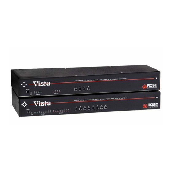
MODELS Vista L-Series models Figure 3. Vista 4 port Figure 4. Vista 8 port Activity LED (ACT) Power LEDs Select LEDs Reset button CPU Select buttons (1 – 4 or 1 – 8) Table 2. Front panel description Vista L-Series Installation and Operations Manual Lit when selected CPU has power. -
Page 13: Table 3. Vista 4Ua/8Ua Description
KVL-4UA rear connectors KVL-8UA rear connectors Label (4U) 1,2,3,4 (*U) 1,2,3,4,5,6,7,8 Monitor Mouse Keyboard Table 3. Vista 4UA/8UA description Vista L-Series Installation and Operations Manual Connector type Description DB25 Computer connectors DB25 Computer connectors HD15F KVM monitor connector MiniDin-6F KVM PS/2 mouse connector MiniDin-6F KVM keyboard... -
Page 14: Table 4. Vista 4Pca/8Pca Description
KVL-4PCA rear connectors KVL-8PCA rear connectors Label Monitor Mouse Keyboard Table 4. Vista 4PCA/8PCA description Vista L-Series Installation and Operations Manual Connector Type Keyboard (MiniDin-6F) Mouse (MiniDin-6F) Video (HD15F) HD15F MiniDin-6F MiniDin-6F Description CPU connectors 1-4 on 4PC model 1-8 on 8PC model... -
Page 15: Vista Cables
Rose Electronics cable part number CAB-WX0606Cnnn or CAB-CX0606Cnnn (DB25 to HD15/PS2/PS2) CPU cable be used. For the Vista models with PC connectors, it is recommended that Rose Electronics cable part number CAB-CXV66MMnnn or CAB-WX66MMnnn (VGA & PS/2 Male to Male cable) be used. -
Page 16: Installation
INSTALLATION Installation Installation of the Vista switch consists of the following steps: It is recommended that the CPUs be powered off. 1. Connect the KVM station to the Vista switch. (Connect the optional power adapter if the unit has the OSD option.) 2. -
Page 17: Step 2 - Connect The Cpus
Step 2 - Connect the CPUs Connect the CPU keyboard, video monitor and mouse ports to the corresponding Vista switches keyboard, video monitor and mouse ports using the appropriate CPU cables as shown in Figure 6. For attached CPUs that use a serial mouse, use adapter ACC-KVM6F9F to connect to the CPUs serial port (do not substitute). -
Page 18: Step 3 - Applying Power
Step 3 - Applying power It is recommended that each connected CPU be booted up starting with the CPU connected to Port #1. Switch the Vista to the CPU port by pressing the appropriate numbered button on the front panel (1-4 or 1-8). Boot that CPU. -
Page 19: Figure 7. Vista To Crystalview
The keyboard, video monitor, and mouse signals can be driven up to 1,000 feet using our CrystalView KVM extenders. VISTA SWITCH UP TO 8 CPUs CAN BE ACCESSED FROM A SINGLE KVM STATION FROM UP TO 1,000’ AWAY Figure 7. Vista to CrystalView Figure 8. -
Page 20: Operating Instructions
OPERATING INSTRUCTIONS Operating instructions The Vista switch is very easy to operate. Computer selection and set-up functions are entered from the keyboard. You can also select computers manually from the Vista’s front panel by using buttons 1-4 or buttons 1-8 depending on your model. - Page 21 Keyboard commands (continued) Command Key Sequence Mode <Ctrl> M x <Enter> command Where: x = 1 for mode 1 x = 2 for mode 2 x = 3 for mode 3 x = 7 for mode 7 x = 8 for mode 8 x = 9 for mode 9 Maximum <Ctrl>...
-
Page 22: Keyboard Command Description
OPERATING INSTRUCTIONS Keyboard commands (continued) Command Computer disconnect. Scan (On) Scan (Off) Reset mouse command Table 5. Keyboard commands Follow each set-up command with the “Keep” command to save the changes. “Keep” command = press and release the left <Ctrl> key, then the “K”... - Page 23 To enable the “Scan mode”, press and release the left <Ctrl> key, then type S. The Vista switch will begin scanning sequentially from its current computer through the remaining computers (as set by the maximum computers command), and then begin again at computer 1. Scan mode (Off) To stop the “Scan mode”, press and release the left <Ctrl>...
- Page 24 Mode 1 - CPU Keyboard = PC Mode 1 (Some IBM’s & PS/1’s) Mode 2 - CPU Keyboard = PC Mode 2 (Most PCs) Mode 3 - CPU Keyboard = Most (RISC) Unix Workstations & Rose Translator Mode 7 - CPU Mouse = 2 Button Serial (Microsoft) (7 Bt)
- Page 25 Reset to initial factory settings The settings that have been previously set and saved in non-volatile memory can be returned to their initial factory settings by holding in buttons “1" and “2” on the front panel and press and release the ”Reset" button.
-
Page 26: On-Screen Display Option
MENUS On-screen display option The on-screen display (OSD) option is available for the Vista L-series models. You can use the OSD to configure the Vista switch, select a computer from a list, display what computer you are switched to and set up security options for the switches’... -
Page 27: Main Menu
Main menu To access the main configuration menu, press and release the left <Ctrl> key, then the F12 key. The main menu will display on the KVM stations video monitor. (See Figure 10) To use the main menu, press the up/down arrow keys to select (highlight) the option needed. -
Page 28: Configure Computer Name
Configure computer name Each computer is initially assigned a computer name, “computer x”, where “x” = 1-8. To change the computer name to one of your choosing, use the up/down arrow keys to select (highlight) the computers name to change. Once selected (highlighted), press enter to clear the present name. -
Page 29: Configure Appearance
Configure appearance The “Configure appearance” menu allows you to change the foreground and background colors, position the computer name on the screen, change the name fadeout time, font, and set up a screen saver type. Figure 12 shows the “Configure appearance” menu. Use the up/down arrow keys to select (highlight) the selection to change. -
Page 30: Appearance Options
Appearance options: Foreground/Background color: Change the foreground and background colors of the computer label showing the selected computer. Solid colors are black, red, green, yellow, blue, magenta, cyan, and white. The transparent colors are: clear, red, green, yellow, blue, magenta, cyan, and white. To change the foreground or background color, first select (highlight) the option and press the space bar to cycle through the list of all the available colors. -
Page 31: Configure Security
Screen saver type: To change the “Screen saver type”, first select (highlight) the option and press the space bar to cycle through the list of all the available screen savers. Stop when the desired screen saver displays. The choices are: Blank screen Fireflies Weaving... - Page 32 If you forget your “Access password”, the person who knows the configure password can enter a new “Access password” for you. If you forget your “Configure password”, contact Rose Electronics Technical Support for instructions. Access time: Automatically log out (disconnects) of the Vista switch after a period of non-activity time.
-
Page 33: Configure Mouse Type
Configure mouse type The “Configure mouse type” menu allows you to change the mouse type for each connected CPU. Change the mouse type on your computers Port Mouse Type PS/2 PS/2 PS/2 PS/2 PS/2 PS/2 PS/2 PS/2 Figure 14. OSD Configure mouse You should only have to change the mouse type if you un-plug the mouse or change the mouse from the auto-detected type. -
Page 34: Configure Keyboard Type
Configure keyboard type The “Configure keyboard type” menu allows you to change the keyboard type. Change the keyboard type on your computers Port Keyboard Type 1 PC2 2 PC2 3 PC2 4 PC2 5 PC2 6 PC2 7 PC2 8 PC2 Figure 15. -
Page 35: Configure Miscellaneous
Configure miscellaneous This menu allows you to change the maximum computer ports and scan time. Miscellaneous Maximum ports Scan time (seconds) Figure 16. OSD Configure miscellaneous Maximum ports: The “Maximum ports” configuration allows you to change the total number of computer ports that are in use. If your using an 8-port switch and only connecting 6 CPUs, changing the maximum ports from 8 to 6 will skip computer ports 7 and 8 during the scan function. -
Page 36: Save
Save The “Save” function, saves all configuration changes that have been made to flash memory. Vista main menu version 2. Names Appearance saver Security Mouse Keyboard Miscellaneous Save Exit PRESS ENTER TO SAVE CONFIGURATION CHANGES PRESS ESCAPE TO RETURN TO THE MAIN MENU Figure 17. -
Page 37: Computer Select Window
Computer select window The OSD option allows you to switch to the connected computers from a list of computer names. Select computer Port Computer 1** computer 1 computer 2 computer 3 computer 4 computer 5 computer 6 computer 7 computer 8 Figure 18. -
Page 38: Troubleshooting
TROUBLESHOOTING TroubleShooting CPU does not boot, keyboard or mouse error received Cable is loose, reseat cable and hit F1 to continue or reboot computer. Wrong cable plugged in, keyboard and mouse cables reversed. Cable is defective; try using a cable from another CPU. If the problem goes away cable is defective. - Page 39 Port on the Vista is defective; try using another port on the Vista. If problem goes away port is defective. Cannot remember the configuration or access password. Call Rose Electronics Technical Support for instructions. Vista L-Series Installation and Operations Manual...
-
Page 40: Maintenance And Repair
This unit does not contain any internal user-serviceable parts. In the event a unit needs repair or maintenance, you must first obtain a Return Authorization (RA) number from Rose Electronics or an authorized repair center. This Return Authorization number must appear on the outside of the shipping container. -
Page 41: Safety
SAFETY Safety This Vista switch has been tested for conformance to safety regulations and requirements, and has been certified for international use. Like all electronic equipment, the Vista switch should be used with care. To protect yourself from possible injury and to minimize the risk of damage to this Unit, read and follow these safety instructions. -
Page 42: Safety And Emc Regulatory Statements
Safety and EMC regulatory statements Safety Information Documentation reference symbol. If the product is marked with this symbol, refer to the product documentation to get product. WARNING A WARNING in the manual denotes a hazard that can cause injury or death. CAUTION A CAUTION in the manual denotes a hazard that can damage equipment. - Page 43 Safety and EMC regulatory statements Informations concernant la sécurité Symbole de référence à la documentation. Si le produit est marqué de ce symbole, reportez-vous à la documentation du produit afin d’obtenir des informations plus détaillées. WARNING CAUTION Ne continuez pas au-delà d’une rubrique WARNING ou CAUTION avant d’avoir bien compris les conditions présentant un danger et pris les mesures appropriées.
-
Page 44: Appendix A. Initial Factory Settings
APPENDICES Appendix A. Initial factory settings Setting Foreground Color Background Color X-position Y-position Fadeout Time Font Screen Saver Screen Saver Time Maximum Ports Scan enable Scan Time Interval Caps/Num lock/Scroll lock PC keyboard Mode Typematic Value Mouse translation Press and hold computer select buttons 1 and 2 and press the reset button to reset the Vista switch to the factory settings listed. -
Page 45: Appendix B. Parts And Cables
Appendix B. Parts and cables CPU Adapter Cables for Models with DB25 Connectors Part Number CAB-WX0606Cnnn* CAB-WX0606C/ATnnn* CAB-CX0606Cnnn** CAB-CX0606C/ATnnn** CPU Adapter Cables for Models with PC Connectors CAB-WX66MMnnn** CAB-WX66MMnnn/AT** CAB-WX66MFnnn** CAB-WX66MFnnn/AT** CAB-CXV66MMnnn** CAB-CXV66MFnnn** ACC-6F5M ACC-KVM6F9F TFR-05D200FSUP-3.5 ACC-KBPWR RM-UL19 RM-UL23 RM-UL24 *Available in standard lengths of 5, 10, and 20 feet Replace nnn with desired length. -
Page 46: Appendix C. General Specifications
33.5 W x 4.45 H x 11.4 D (cm) 3 lb. 0 to 55°C., 0% to 80% non-condensing relative humidity Supplied by computers KVL-4UA DB25 Female KVL-8UA DB25 Female KVL-4PCA HD15F/MD6F/MD6F KVL-8PCA HD15F/MD6F/MD6F HD15F VGA video MD6F MD6F Fully shielded, black painted steel with polyester graphic overlay panel... -
Page 47: Appendix D. Rack Mount Instructions
Appendix D. Rack mount instructions The optional rack mount kit includes the following items: Two black anodized mounting brackets. Four 6 - 32 x 3/8” flat head mounting screws. To rack mount your Vista switch, attach the two rack mounting brackets to your unit with the short flange against the unit using the four screws provided. -
Page 48: Appendix E. Rack Mount Illustration
Appendix E. Rack mount illustration Rack mount kits come with two (2) mounting brackets and four (4) screws to attach the Vista KVL chassis to the mounting brackets. Vista L-Series Installation and Operations Manual... -
Page 49: Appendix F. Typematic Rate
Appendix F. Typematic rate Typematic Command Press the left <Ctrl> key, type “A”, enter the typematic value (1-3 digit) followed by <Enter>. The typematic value is determined from the following tables using the equation: Typematic Value = Rate value + Delay Value. Pick the desired rate in keys/sec. - Page 50 INDEX Index Appearance ... 23, 24 Button ... 2, 3, 19, 27, 38, 40 Cables ... 3, 9, 10, 11, 32, 33, 41 Colors ... 1, 2, 23, 24 CPU ... 1, 2, 3, 4, 6 DB25... 1, 2, 4, 9, 39, 40 Factory Settings...
- Page 52 10707 Stancliff Road Phone: (281) 933-7673 Houston, Texas 77099 WWW.ROSE.COM...
Need help?
Do you have a question about the KVL-4PCA and is the answer not in the manual?
Questions and answers