Table of Contents
Advertisement
Quick Links
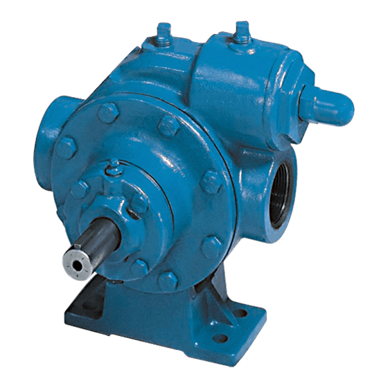
BLACKMER LIQUEFIED GAS PUMPS
INSTALLATION OPERATION AND MAINTENANCE INSTRUCTIONS
MODELS: CRLR1.25, CRL1.25, CRL1.5
Patent Protected by U.S. Patent 6030191 and Related Foreign Patents.
TABLE OF CONTENTS
Technical Data ................................................... 2
Initial Pump Start Up Information....................... 2
Pre-Installation Cleaning.................................... 3
Location and Piping ........................................... 3
Pump Relief Valve and Bypass valve ................ 3
Check Valves ..................................................... 4
Mounting ............................................................ 4
Coupling Alignment............................................ 4
Pump Rotation ................................................... 4
To Change Pump Rotation ................................ 4
Pre-Start Up Check List ..................................... 5
Start Up Procedures .......................................... 5
Relief Valve Setting and Adjustment ................. 5
Strainers ............................................................... 6
Lubrication ............................................................ 6
Vane Replacement ............................................... 7
Pump Disassembly............................................... 7
Parts Replacement ............................................... 7
Pump Assembly.................................................... 8
TROUBLE SHOOTING ............................................. 10
NOTE: Numbers in parentheses following individual parts
indicate reference numbers on Blackmer Parts List No.
701-A01.
Blackmer pump manuals and parts lists may be obtained
from Blackmer's website (www.blackmer.com) or by
contacting Blackmer Customer Service.
FOR CO
SERVICE
2
Page
962300
INSTRUCTIONS NO. 701-A00
SAFETY DATA
This is a SAFETY ALERT SYMBOL.
When you see this symbol on the product, or in the
manual, look for one of the following signal words and
be alert to the potential for personal injury, death or
major property damage
Warns of hazards that WILL cause serious personal
injury, death or major property damage.
Warns of hazards that CAN cause serious personal
injury, death or major property damage.
Warns of hazards that CAN cause personal injury
or property damage.
NOTICE:
Indicates special instructions which are very
important and must be followed.
NOTICE:
Blackmer CO
pumps MUST only be installed in
2
systems which have been designed by qualified
engineering personnel. The system MUST conform to
all applicable local and national regulations and safety
standards.
This manual is intended to assist in the installation and
operation of the Blackmer CO
kept with the pump.
Blackmer CO
pump service shall be performed by
2
qualified technicians ONLY. Service shall conform to
all applicable local and national regulations and safety
standards.
Thoroughly review this manual, all Instructions and
hazard warnings, BEFORE performing any work on the
Blackmer CO
pumps.
2
Maintain ALL system and Blackmer CO
operation and hazard warning decals.
Section
701
Effective
Nov 2007
Replaces
Oct 2007
pumps, and MUST be
2
pump
2
Advertisement
Table of Contents

Related Manuals for Dover BLACKMER CRLR1.25


Summary of Contents for Dover BLACKMER CRLR1.25
-
Page 1: Table Of Contents
962300 BLACKMER LIQUEFIED GAS PUMPS INSTRUCTIONS NO. 701-A00 FOR CO SERVICE Section INSTALLATION OPERATION AND MAINTENANCE INSTRUCTIONS Effective Nov 2007 Replaces Oct 2007 MODELS: CRLR1.25, CRL1.25, CRL1.5 Patent Protected by U.S. Patent 6030191 and Related Foreign Patents. SAFETY DATA This is a SAFETY ALERT SYMBOL. When you see this symbol on the product, or in the manual, look for one of the following signal words and be alert to the potential for personal injury, death or... -
Page 2: Pump Data
SAFETY DATA Failure to disconnect and lockout Failure to disconnect and lockout electrical power or engine drive before electrical power before attempting attempting maintenance can cause maintenance can cause shock, burns or severe personal injury or death death Hazardous Hazardous voltage. machinery can Can shock, burn or cause serious... -
Page 3: Installation
INSTALLATION NOTICE: Check alignment of pipes to pump to avoid strains which Blackmer pumps must only be installed in systems might later cause misalignment. See Figure 2. Unbolt designed by qualified engineering personnel. System flanges or break union joints. Pipes should not spring design must conform with all applicable regulations and away or drop down. -
Page 4: Check Valves
INSTALLATION CHECK VALVES COUPLING ALIGNMENT The use of check valves or foot valves in the supply tank is The pump must be directly coupled to a gear reducer and/or not recommended with self-priming, positive displacement driver with a flexible coupling. Verify coupling alignment after pumps. -
Page 5: Operation
OPERATION Disconnecting fluid or pressure Operation without guards in place can containment components during pump cause serious personal injury, major operation can cause serious personal property damage, or death. injury or property damage. Hazardous pressure Do not operate can cause serious without guard personal injury or in place... -
Page 6: Maintenance
MAINTENANCE Failure to disconnect and lockout Failure to disconnect and lockout electrical power before attempting electrical power before attempting maintenance can cause shock, burns maintenance can cause shock, burns or or death death Hazardous Hazardous voltage. machinery can Can shock, burn or cause serious cause death. -
Page 7: Vane Replacement
MAINTENANCE VANE REPLACEMENT 4. Remove the outboard bearing cover capscrews (28) and slide the outboard bearing cover (27A) and gasket (26) off NOTICE: the shaft. Discard the bearing cover gasket. Maintenance shall be performed by qualified technicians only. Following the appropriate procedures and 5. -
Page 8: Pump Assembly
MAINTENANCE PUMP ASSEMBLY b. If the pump is equipped with the four-vane rotor and Before reassembling the pump, inspect all component shaft (13A), hold the two bottom vanes (14) in place parts for wear or damage, and replace as required. Wash while inserting the two push rods (77). - Page 9 MAINTENANCE 17. Attach a new bearing cover gasket (26) and the inboard bearing cover (27) to the inboard head (20). Install the outboard bearing cover (27A) and a new gasket to the outboard head. Make sure the grease fittings (76) on the bearing covers are accessible.
-
Page 10: Troubleshooting
TROUBLESHOOTING NOTICE: Maintenance shall be performed by qualified technicians only, following the appropriate procedures and warnings as presented in this manual. SYMPTOM PROBABLE CAUSE 1. Pump not wetted. Pump Not Priming 2. Worn vanes. 3. Internal control valve closed. 4. Strainer clogged. 5. - Page 11 TROUBLESHOOTING ….. continued 1. O-rings not compatible with the liquids pumped. Mechanical Seal Leakage 2. O-rings nicked, cut or twisted. 3. Shaft at seal area damaged, worn or dirty. 4. Ball bearings overgreased. 5. Excessive cavitation. 6. Mechanical seal faces cracked, scratched, pitted or dirty. 1.
- Page 12 ® Sliding Vane Pumps: 5 to 2200 GPM System One Centrifugal Pumps Refined Fuels, Liquefied Gases, Process, 10 to 7500 GPM Transport, Marine Process, Marine Abaque Peristaltic Hose Pumps C-Series Eccentric Disc Pumps 0.5 to 220 GPM Stainless Steel & Ductile Iron, 1 to 150 GPM Shear Sensitive, Food, Process High Lift, Solids, Abrasives Rotary Vane and Screw Compressors...
Need help?
Do you have a question about the BLACKMER CRLR1.25 and is the answer not in the manual?
Questions and answers