Table of Contents
Advertisement
Quick Links
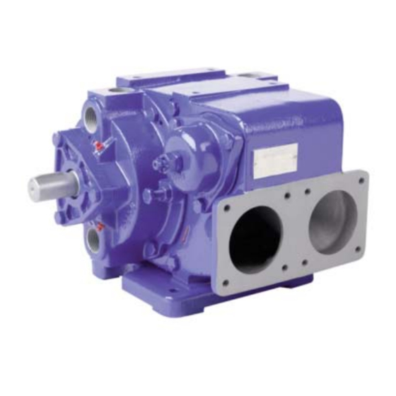
CC8-65 EP pump
Z.I. La Plaine des Isles - F 89000 AUXERRE - FRANCE
Tel. : +33 (0)3.86.49.86.30 - Fax : +33 (0)3.86.49.87.17
contact@mouvex.com - www.mouvex.com
INSTRUCTIONS 1010-G00 e
Section
1010
Effective
May 2013
Replaces
April 2011
Translation of the
original instructions
INSTALLATION
OPERATION
MAINTENANCE
Your distributor :
Advertisement
Table of Contents

Subscribe to Our Youtube Channel
Related Manuals for Dover Mouvex CC8-65 EP


Summary of Contents for Dover Mouvex CC8-65 EP
- Page 1 INSTRUCTIONS 1010-G00 e Section 1010 Effective May 2013 Replaces April 2011 Translation of the original instructions CC8-65 EP pump INSTALLATION OPERATION MAINTENANCE Your distributor : Z.I. La Plaine des Isles - F 89000 AUXERRE - FRANCE Tel. : +33 (0)3.86.49.86.30 - Fax : +33 (0)3.86.49.87.17 contact@mouvex.com - www.mouvex.com...
-
Page 2: Overall Dimensions
1. PRESENTATION Heating-shell ports Bypass Arrow rotation Bypass adjustment End plate dismountling Arrow suction Pump plate S Special baseplate for clearing heating lines Drain/Vaccum plug - G1/2 Drain/Pressure plug M10 Mounting point for temperature sensor V2-S1 2. OVERALL DIMENSIONS V2-S1 Weight : 61 kg The pump has only one direction ;... - Page 3 3. CHARACTERISTICS Speed Maximum Flow Max. ref. Input of rotation viscosity at 600 Cst pressure power (rpm) (Cst) (bar) at 6 b. - kw The CC8-65 EP pump is delivered exclusively with an adjus- table-spring bypass. 2000 Do not exceed the maximum permissible pressure, or 6 bar. 2000 1500 4.
- Page 4 5. ASSEMBLY / DISMANTLING (continued) 5.5 To change the vanes Finish fitting the end-plate by gradually screwing the 2 nuts 412 onto the 2 screws 411. Open the pump on the drive side. Remove from the remaining end-plate the 4 screws 410, the 2 screws 411 and take out the vanes 317 as well as the 3 pushrods 318.
- Page 5 5. ASSEMBLY / DISMANTLING (continued) Remove the 3 screws 856 from the bypass cap. Take out the spring 824. Remove the poppet 823 by pulling on its cylindrical sec- tion with the fingers. Check the bypass. Clean all parts prior to reassembly. 5.7 Dismantling and reassembly of the bypass for visit DISMANTLING...
-
Page 6: Spare Parts
7. SPARE PARTS ° Sets and parts available to supply. DESIGNATION SET OF SCREWS (410 + 411 + 412 + 723 + 856) ° PUMP SET GASKETS (126 + 128 + 403 + 807) ° ° COMPLETE BODY Body Pump plate Plate rivet °... - Page 7 7. SPARE PARTS (continued) DESIGNATION COMPLETE SHAFT ° ° EQUIPED SHAFT Shaft Bushing ° SET OF KEYS, COMPLETE Shaft end key Sliding rotor key Retaining ring Shaft end protector MONOBLOC GASKET, COMPLETE ° Stationary part Stationary part seal ................(see 699) Cuvette seal ..................(see 699) Spring guide Spring...
- Page 8 7. SPARE PARTS (continued) VARIANTES DESIGNATION COMPLETE PUMP BASEPLATE ° Baseplate bolt Lock washer Pump baseplate COMPLETE BALL BEARING FOR SPEED REDUCER ° 700a Bearing ° Reduction gear side plate Grease nipple ° Shim Side plate screw Protection ring Spacer Reductor screw Lock washer When ordering spare parts, mention :...
Need help?
Do you have a question about the Mouvex CC8-65 EP and is the answer not in the manual?
Questions and answers