Table of Contents
Advertisement
Quick Links
CC10 Series pumps are covered 36 months by warranty within the limits mentioned in our General Sales Conditions.
In case of a use other than that mentioned in the Instructions manual, and without preliminary agreement of MOUVEX, warranty
will be canceled.
Z.I. La Plaine des Isles F 89000 AUXERRE FRANCE
Tel. : +33 (0)3.86.49.86.30 Fax : +33 (0)3.86.49.87.17
contact.mouvex@psgdover.com www.mouvex.com
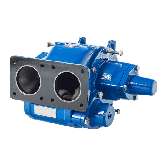
CC10‐24 pump
Construction A
WARRANTY :
INSTRUCTIONS 1010P00 e
Section
1010
Effective
September 2020
Replaces
February 2020
Original instructions
INSTALLATION
OPERATION
MAINTENANCE
Your distributor :
Advertisement
Table of Contents

Related Manuals for Dover PSG Mouvex CC10-24


Summary of Contents for Dover PSG Mouvex CC10-24
- Page 1 INSTRUCTIONS 1010P00 e Section 1010 Effective September 2020 Replaces February 2020 Original instructions CC10‐24 pump Construction A INSTALLATION OPERATION MAINTENANCE WARRANTY : CC10 Series pumps are covered 36 months by warranty within the limits mentioned in our General Sales Conditions. In case of a use other than that mentioned in the Instructions manual, and without preliminary agreement of MOUVEX, warranty will be canceled.
-
Page 2: Table Of Contents
TANK TRUCK PUMP SAFETY, STORAGE, INSTALLATION AND MAINTENANCE INSTRUCTIONS MODEL : CC10-24 A Page TABLE OF CONTENTS 1. OPERATING LIMITS ........3 2. -
Page 3: Operating Limits
1. OPERATING LIMITS Speed range Max flow rate Max pressure Required power (rpm) (bar) (Kw) 450 ► 1500 450 ► 920 450 ► 1000 450 ► 750 Viscosity : < 40 cSt Temperature range allowed : 20°C to +80°C Products authorised : Clean petroleum product Other products : Contact us The pumps CC10 are delivered with spring (5 or 10 bar) depending on the application. -
Page 4: Overall Dimensions
2. OVERALL DIMENSIONS NT 1010P00 09 20 CC1024 A e 4/18... - Page 5 2. OVERALL DIMENSIONS (continued) NT 1010P00 09 20 CC1024 A e 5/18...
-
Page 6: Installation
3. INSTALLATION 3.1 Choice of pump 3.5 Piping assembly To obtain the service expected from a MOUVEX pump, regar In order to achieve the best usage conditions, it is important ding both performance and longevity, it is vital that the type to take the following recommendations into account when it of pump, its speed and the materials used for its construction comes to fitting pipes :... -
Page 7: Direct Drive By Motor
4. DIRECT DRIVE BY MOTOR 4.1 Installation of units 4.2 Alignment of motor/pump and reduction gearbox/pump shafts WARNING WARNING BE CAREFUL WITH THE WEIGHT OF THE OPERATION WITHOUT THE SHAFT PRO- PARTS WHEN THEY ARE BEING REMOVED. TECTOR CAN CAUSE SERIOUS PERSONAL INJURY, MAJOR PROPERTY DAMAGE OR DEATH. -
Page 8: Electric Motors
4. DIRECT DRIVE BY MOTOR (continued) 4.3 Electric motors This check should be done with no liquid being pumped, and both the inlet and discharge circuits vented to avoid generating WARNING unexpected pressure (on the inlet side, for example). This will avoid damaging either the pump or the system. -
Page 9: Use
6. USE 6.3 Startingup the pump The operator should remain nearby the equipment throughout the use to ensure the proper functioning of the system. WARNING 6.1 Pumping hot liquids CAUTION FAILURE TO RELIEVE SYSTEM PRESSURE PRIOR TO PERFORMING PUMP SERVICE OR MAINTENANCE CAN CAUSE PERSONAL INJURY OR PROPERTY DAMAGE. -
Page 10: Protection From Frost
6. USE (continued) 6.7 Protection from frost 6.8 Restarting Follow the standard startup procedure for the pump/ If there is a risk of frost with the product contained in the pump, motordriven pump, as well as the instructions below. it is necessary to drain the body after each use as follows : Step 1 : Turn the pump by hand to make sure the parts move freely. -
Page 11: Dismantling - Reassembly
8. DISMANTLING - REASSEMBLY WARNING WARNING DISCONNECTING THE FLUID OR PRESSURE CONTAINMENT COMPONENTS DURING DISCONNECT THE ELECTRICITY SUPPLY PUMP OPERATION CAN CAUSE SERIOUS BEFORE ANY MAINTENANCE OPERATION. PERSONAL INJURY, DEATH OR MAJOR PROPERTY DAMAGE. Hazardous pressure Dangerous voltage. can cause Can cause personal injury injury and death. -
Page 12: Dismantling On Drive Side
8. DISMANTLING REASSEMBLY (continued) 8.3 Reassembly When the endplate is free on the shaft, hold it by hand sup porting it. When putting the endplate back into place, take care to have the shaft seal drive lugs facing the notches on rotor. Refit in the endplate the Nilos ring 733, the ball bearings 703 and the spacer 734. -
Page 13: Changing Shaft Seal
10. CHANGING SHAFT SEAL IMPORTANT : Mechanical seal components must never be put on friction faces without protection sheets. Reassembly IMPORTANT Lubricate the bore of the endplate which takes the shaft seal. Make sure that the seals 605, 613 and the shaft seal are in good condition. -
Page 14: Bypass
11. BYPASS The bypass must be set depending on the needs and the limitations of the installation. A preset can be operated, please refer to the information below, but it has to be followed up by a checkup on the installation. 11.1 Mechanical bypass Dismantling Setting... -
Page 15: Pneumatic Bypass
11. BYPASS (continued) 11.2 Pneumatic bypass These curves indicate the nominal air pressure when the dis The pressure regulator preset can be operated, please refer to charge valve is closed, it will be necessary to adjust this pres the curve below, but it has to be followed up by a checkup on sure according to the installation, but the hydraulic pressure the installation : in the pump must, in no case, exceed 10 bar. -
Page 16: Maintenance
12. MAINTENANCE 12.1 Lubrication 12.3 Cleaning the filter Ball bearings are lubricated for life and don’t require any grease The pump should always be protected against possible foreign adding. matter by means of a filter connected into the suction pipe. Check the cleanliness of the filter mesh from time to time as 12.2 Inspection of the vanes a.partly clogged filter could starve the pump and reduce its output. -
Page 17: Storage
14. STORAGE 14.1 Short duration (≤ 1 month) 14.2 Long duration (> 1 month) We recommend the following procedure for longer periods of WARNING storage : The recommendations from the manufacturer should be fol lowed if the pump is stored with its gear motor. IF PUMPING HAZARDOUS OR TOXIC FLUIDS, Pump ports should be filled with a noncorrosive liquid that it THE SYSTEM MUST BE FLUSHED PRIOR TO... -
Page 18: Certificate Of Conformity
16. CERTIFICATE OF CONFORMITY NT 1010P00 09 20 CC1024 A e 18/18...
Need help?
Do you have a question about the PSG Mouvex CC10-24 and is the answer not in the manual?
Questions and answers