
Related Manuals for Dover PSG Wilden P1


Summary of Contents for Dover PSG Wilden P1
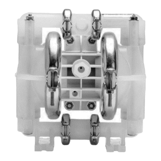
- Page 1 ENGINEERING OPERATION & MAINTENANCE P1 Clamped Plastic Pump Where Innovation Flows WIL-10140-E-08...
-
Page 2: Table Of Contents
Contents Section 1: Precautions - Read First! Section 2: Wilden Pump Designation System Section 3: How It Works —Pump & Air Distribution System Section 4: Dimensional Drawings P1 Pla st ic Section 5: Performance P1 Pla st ic R ubb er - F i tte d P1 Pla st ic T PE - F it te d P1 Pla st ic P TF E- F i tte d Su ct ion - Li ft Cur ve s... - Page 3 PSG, a Dover Company, except as described by the terms of those agreements. This is a non-contractual document. 01-2019.
-
Page 4: Section 1: Precautions - Read First
Section 1 Precautions - Read First! CAUTION: The process fluid and cleaning fluids CAUTION: Do not apply compressed air to the exhaust port must be chemically compatible with all wetted pump — pump will not function components (see E4). CAUTION: Do not over-lubricate air supply — excess CAUTION: Pumps should be thoroughly flushed lubrication will reduce pump performance. -
Page 5: Section 2: Wilden Pump Designation System
Section 2 W I L D E N P U M P D E S I G N A T I O N S Y S T E M P1 ORIGINAL™ PLASTIC LEGEND / X X X X X / XXX / XX / X XX / XXXX MODEL O-RINGS... -
Page 6: Section 3: How It Works -Pump & Air Distribution System
HOW IT WORKS — PUMP Section 3 The Wilden diaphragm pump is an air-operated, placement, self-priming pump. These drawings show the flow pattern through the pump upon its initial stroke. It is assumed the pump has no fluid in it prior to its initial stroke. FIGURE 1 The air valve directs pressurized FIGURE When... -
Page 7: Section 4: Dimensional Drawings
DIMENSIONAL DRAWING P1 Plastic DIMENSIONS ITEM METRIC (mm) STANDARD (inch) ® Wilden WIL-10140-E-08... -
Page 8: Section 5: Performance
Section 5 PERFORMANCE P1 PLASTIC RUBBER-FITTED Height ........218 mm (8.6") Width ........208 mm (8.2") Depth ........203 mm (8.0") Est. Ship Weight ... Polypropylene 4 kg (9 lbs) PVDF 5 kg (11 lbs) PTFE PFA 6 kg (12 lbs) Air Inlet........ -
Page 9: P1 Plastic Ptfe-Fitted
PERFORMANCE P1 PLASTIC PTFE-FITTED Height ........218 mm (8.6") Width ........208 mm (8.2") Depth ........203 mm (8.0") Est. Ship Weight ... Polypropylene 4 kg (9 lbs) PVDF 5 kg (11 lbs) PTFE PFA 6 kg (12 lbs) Air Inlet........6 mm (1/4") Inlet ........ -
Page 10: Su Ct Ion - Li Ft Cur Ve S
S U C T I O N L I F T C U R V E S P1 PLASTIC SUCTION - LIFT CAPABILITY Suction lift curves are calibrated for pumps operating at 305 m (1,000') above sea level. This chart is meant to be a guide only. -
Page 11: Section 6: Suggested Installation, Operation
Section 6 Suggested Installation, Operation, Maintenance and Troubleshooting The Pro-Flo model P1 has a 13 mm (1/2") inlet and 13 mm (1/2") outlet • Elevation: Selecting a site that is well within the pump’s ® and is designed for flows to 56.8 lpm (15 gpm). The P1 Plastic pump is dynamic-lift capability will assure that loss-of-prime issues will manufactured with wetted parts of pure, unpigmented PVDF, PTFE PFA be eliminated. - Page 12 Suggested Installation, Operation, Maintenance and Troubleshooting This illustration is a generic representation of an air-operated double-diaphragm pump. NOTE: In the event of a power failure, the shut-off discharge by partially closing a valve in the discharge line of the pump. This action increases friction loss which reduces flow rate.
- Page 13 Suggested Installation, Operation, Maintenance and Troubleshooting Troubleshooting Pump will not run or runs slowly. 1. Ensure that the air inlet pressure is at least 0.3 bar (5 psig) 3. Check for sticking ball check valves. If material being pumped is above startup pressure and that the differential pressure (the not compatible with pump elastomers, swelling may occur.
-
Page 14: Section 7: Disassembly / Reassembly
Section 7 Disassembly / Reassembly Pump Disassembly CAUTION: Before any maintenance or repair is attempted, the compressed air Tools Required: line to the pump should be disconnected and all air pressure allowed to bleed from the pump. Disconnect all intake, discharge, and air lines. Drain the pump •... - Page 15 Disassembly / Reassembly Step 3 Step 4 Remove the discharge valve balls, seats and o-rings from the Remove the top manifold and lift the center section off the discharge manifold and inspect for nicks, gouges, chemical inlet manifold. attack or abrasive wear. Replace worn parts with genuine Wilden parts for reliable performance.
- Page 16 Disassembly / Reassembly Step 7 Step 8 Inspect o-rings for wear or damage and replace if necessary. Use a 11 mm (7/16") wrench to remove one set of clamp bands PTFE o-rings should be replaced when reassembled. that secure one liquid chamber to the one-piece center section. Step 9 Step 10 Lift the liquid chamber away from the center section to expose the...
- Page 17 Disassembly / Reassembly Step 11A Step 11B Step 12 2) The outer piston, diaphragm, inner NOTE: Due to varying torque values, one To remove the diaphragm assembly from piston, and disc spring separate from the of the following two situations may occur: the shaft, secure shaft with soft jaws (a vise shaft which remains connected to the fitted with plywood or other suitable material)
-
Page 18: Si Ng Le - Pi Ec E M Ani Fo Ld Di S Ass Emb Ly /R Ea Sse Mb Ly
Disassembly / Reassembly Single-Piece Manifold CAUTION: Before any maintenance or repair is attempted, the compressed air line to Tools Required: the pump should be disconnected and all air pressure allowed to bleed from pump. Disconnect all intake, discharge, and air lines. Drain the pump by turning it upside •... - Page 19 Disassembly / Reassembly Step 1 Step 2 Step 3 Remove discharge manifold. It is now Remove the o-ring, ball cage and ball Using an appropriate sized Allen wrench, possible to inspect the outboard o- rings. valve from the water chamber. It is now remove clamp bands that hold the possible to inspect these parts.
-
Page 20: Air Valve / Center Section Disassembly
Disassembly / Reassembly Air Valve / Center Section Disassembly CAUTION: Before any maintenance or repair is attempted, the compressed air line to the pump Tools Required: should be disconnected and all air pressure allowed to bleed from the pump. Disconnect all intake, •... - Page 21 Disassembly / Reassembly Step 6 Step 4 Step 5 Remove pilot spool sleeve retaining snap Remove air valve spool from air valve body Remove air valve end cap to expose air ring on both sides of center section with by threading one air valve bolt into the end of valve spool by simply lifting up on end cap snap ring pliers.
-
Page 22: Reassembly Hints & Tips
Disassembly / Reassembly Reassembly Hints & Tips Upon performing applicable maintenance to the air Ensure proper mating of liquid chambers to manifolds prior • distribution system, the pump can now be to tightening vertical bolts. Overhang should be equal on reassembled. - Page 23 Gasket Kit / Installation P1 PVDF and Ultrapure pumps come standard with expanded PTFE Carefully prepare sealing surfaces by removing all debris and foreign Gasket Kits (P/N 01-9501-99) for all sealing surfaces. P1 Poly pumps matter from diaphragm bead and all mating surfaces. If necessary, come standard with expanded PTFE Gasket Kits (P/N 01-9500-99) for smooth or deburr all sealing surfaces.
-
Page 24: Section 8: Exploded View And Parts List
Section 8 Exploded View and Parts Listing P1 PLASTIC EXPLODED VIEW RUBBER- FITTED ® Wilden WIL-10140-E-08... - Page 25 Exploded View and Parts List Qty. Per P1/ PPPPP P1/ KPPPP Item Part Description Pump Pro-Flo Air Valve Assembly 01-2010-20 01-2010-20 ® End Cap 01-2332-20 01-2332-20 O-Ring, End Cap 01-2395-52 01-2395-52 Gasket, Air Valve 01-2615-52 01-2615-52 Screw, HSHC, Air Valve 1/4"-20 01-6001-03 01-6001-03 Nut, Hex, 1/2"-20...
-
Page 26: P1 Pla St Ic P Tf E- F I Tte D
Exploded View and Parts Listing P1 PLASTIC EXPLODED VIEW PTFE - FITTED ® Wilden WIL-10140-E-08... - Page 27 Exploded View and Parts List Item Part Description Qty. Per P1/ PPPPP P1/ PPPPP/0502 P1/ KKPPP P1/ KKPPP/0502 Pump Pro-Flo Air Valve Assembly 01-2010-20 01-2010-20 01-2010-20 01-2010-20 ® End Cap 01-2332-20 01-2332-20 01-2332-20 01-2332-20 O-Ring, End Cap 01-2395-52 01-2395-52 01-2395-52 01-2395-52 Gasket, Air Valve 01-2615-52...
-
Page 28: Section 9: Elastomer Options
Section 9 Elastomer Options P1 Plastic Material Diaphragm P/N Valve Ball P/N Valve Seat* P/N Valve Seat O-Ring P/N Manifold O-Ring P/N Polyurethane 01-1010-50 01-1080-50 01-1200-50 01-1300-50 Buna-N 01-1010-52 01-1080-52 01-1260-52 01-1300-52 01-1010-53 01-1080-53 01-1120-53 Wil-Flex™ 01-1010-58 01-1080-58 00-1260-58 00-1260-58 Saniflex™... - Page 29 Notes ® Wilden WIL-10140-E-08...
- Page 30 Notes ® Wilden WIL-10140-E-08...
- Page 31 Notes WIL-10140-E-08 ® Wilden...
- Page 32 22069 Van Buren Street Grand Terrace, CA 92313-5651 USA 1 (909) 422-1730 • F: 1 (909) 783-3440 psgdover.com Where Innovation Flows ® reserves right to modify information and illustrations contained this document without prior notice. This is non-contractual document. 05- 2018 WIL-10140-E-08 ®...
Need help?
Do you have a question about the PSG Wilden P1 and is the answer not in the manual?
Questions and answers